


THE DESIGN OF THE TRACTOR-LORRY.
Page 14
Page 15
Page 16
If you've noticed an error in this article please click here to report it so we can fix it.
SINCE THE introduction of the Knox tractor and semi-trailer into this, country about ten
. years ago, many designers have been at work on this type of vehicle. To many, no doubt, it may seem a very simple proposition to attach a twowheeled trailer to the back of an ordinary fourwheeled motor wagon, but experience in the running of these vehicles has shown, beyond all doubt, that there are many features which require special attention in design. It is well known that, for years, the two-wheeled pole trailer. has,been used in conjunction with the ordinary motor wagon fitted with a swivelling bolster for conveying long girders, timber togs, etc. These have, however, always been looked upon as a special arrangement for carrying heavy, indivisible loads, whereas the object now is to carry the largest possible' loads at the highest speed and smallest cost, on the permitted axle weights.
It is interesting to note, in this respect, that the utility of this type of vehicle was foreseen nearly a hundred years ago. In Alexander Gordon's book on steam carriages, published in 1836, the author advocated " the use of a separate steamer, which can be standardized, to which a pairwheeled carriage may be attached for the conveyanee of six or seven passengers." .
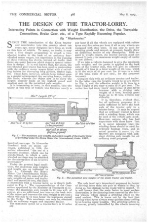
Lander the present legal condi. tions, the maximum axle weights and length are as indicated in Fig. 1. Although the Heavy Motor Car (Amendment) Order, 1922, states that the sum of all the axle weights of motor and trailer shall not exceed 22 tons, this limit is irnpossibk with a tractor lorry, as is clearly indicated in Fig, 1. The recommendation of .the Committee appointed by-the Ministry of Transport to increase the the maximuni axle weight to 10 tons will, of course, give an additional two tons on the back axle of the motor and increase the total weight to 20* tons; which will still be 14 tons below the maximum stated in the Order. This maximum can only be obtained with an ordinary wagon and separate trailer.
The maximum speed for a tractor-lorry is 12 miles 012
AVSW 6:27011S Fig. 2.—The pa per hour if all the wheels are equipped with rubber tyres and five miles per hour if all or any wheels are equipped with steel tyres. It can only be used for carrying goods and cannot, at present, legally draw an additional trailer of any description. With regard to weight empty, the tractor portion must not exceed 7i toes; the maximum weight empty of trailer is not defined.
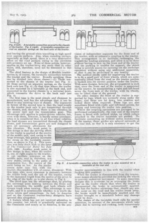
If we take a vehicIe.designed to give the maximum axle weights, and the power is applied to the back axle of the tractor only, this will give an adhesive weight of 8 tons in a total weight of 184 tons, which is in the ratio of•43 per cent. (or 10 tons in a total of 20* tons, ratio 49 per cent., for the proposed increase).. ,Compare this with an ordinary tractor and trailer. In the latter ease the weights would be as are shown in Fig. 2, and the adhesive weight is 54 tons in a total weight of 204 tons—a ratio of 27 per cent. The writer has hail many years' experience of stcel-tyred tractors with a driving axle weight of 5 tons, hauling gross loads up to 20 tons without any difticul ty.
It-, is, therefore, evident Olaf,. for all ordinary .purposes, it is quite sufficient to drive the back aide of the tractor only in a tractor-lorry. It may be argued that an ordinary tractor is fitted with a winding drum, which can be used if the vehicle gets stuck. However, 'anyone •who has had experience with these know Lhat kitzt-"Axie k/tik-ve it is never intended that the winding drum should be used for ordinary haulage work, and in actual practice it never is; the tractors are designed with sufficient driving axle weigfit for all ordinary road purposes, The only (and very important) argument in favour of driving more than one pair of wheels is that, by doing so, less damage to the roads will be caused. It is well known that the main factor in road surface destruction is the shearing force exerted by the driving wheels, which causes a grinding effect on the road surface. This is borne out by the fact that driving-wheel tyres always wear quicker than trailing tyres bearing equal weights. The grinding action is, of course, greatly intensified by the wheels bouncing
and leaving the ground when travelling at high speed over uneven surfaces. Also, when rounding corners, especially at high speed, there is a very destructive effect on the road surface, owing to the enormous side pressure set up. None of these points, however, applies tri the tractor-lorry any more than to other types, and, therefor.e, need not be discussed in this article.
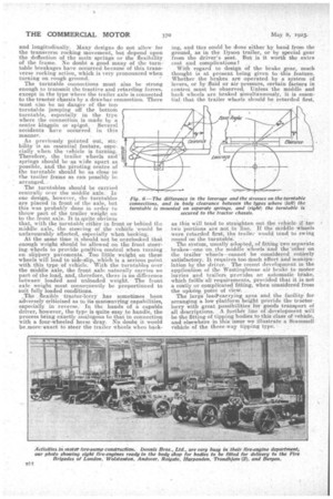
The chief feature in the design of flexible tractor' lorries is, of course, the turntable connection between the tractor and the trailer. Broadly speaking, these can be divided into three classes :=(1) Those connected to the chassis of the tractor (see Fig. 3); (2) those carried on separate springs on the tractor back axle (see Fig. 4); (3) that type where the trailer is also mounted on a turntable at the back end, and connected to the tractor chassis by a universal ioint,‘ which transmits the drive to the hack axle (see Fig. 5).
The first type is the most simple and cheapest to manufacture, and has the advantage that it can be fitted to any existing type of chassis. The argument in favour of the second type is that the load-weight on the tractor back axle is not transmitted through the chassis, and, therefore, there is less vibration Oil the power unit and the transmission gear. This advantage only applies to petrol-driven vehicles, but, even with these, however, it hardly seems necessary, when it is considered that in all four-wheel vehicles, the load stresses are transmitted through the chassis frame, and transmission gears are now designed to give all necessary allowances for this vibration. The weak point in this design is that the driving effort to the trailer is applied at the centre of the middle axle, and, owing to the large leverage, this greatly increases the stress on the turntable connection, as shown in Fig. 6. This question was fully dealt with in the issue of The Commercial Motor for July 11th, 1922. Another weak point in this design is that when the trailer is, say, at right angles to the tractor, it can oscillate sideways on the middle axle, and is, therefore, not very stable, owing to the point of suspension (i.e., the centre of the axle) being so law. As the trailer conies more into line with the tractor, this tendency will of course, disapPear. With this type, also, more clearance is necessary between the trailer body and the cab of the tractor, owing to the increased length from the centre of the pivot to the edge Of the body, ,as is alse shown in Fig. 6.
The third type has the advantage that, by placing the universal Joint midway between the front and back turntables, the middle and back wheels will always, track when turning. This advantage is very slight,•,and it is questionable whether it is worth the extra Joints and connections. In fact, in America and on the Continent tractor-lorry designers 'have ignored this altogether. ,
A feature which has not yet received attention in this country, but which is practically universal on the Continent and nearly so in America, is the pro , vision of independent. Supports for the front end of the trailer, with an automatic coupling to the tractor. This arrangement is to facilitate 'exchanging the trailef.rfor lottcling.purposes, and allow it to be done without having to Jack up the front end of the trailer and use packing or trestles for support, the 'object being to provide means for carrying out the exchange Operation without using any additional apparatus, so that it Can be performed in any locality. The method chiefly used for supporting the trailer is to fit a small pair of front wheels, which are automatically lifted from the road as the tractor portion is 'backed into its correct position under thn trailer. With some designs, however, the arrangement is such that, once the front end of the trailer is supported on the tractor, by manipulating a right and left-hand screw the front axle of the trailer, with its wheels, can be lifted clear of the ground. On other designs the front of the trailer is supported by legs, Which are normally slung under the frame., and these are let down into position and locked there when required. These legs are also sometimes fitted with rightand left-hand screws, for raising and lowering the trailer into position.
Where the coupling operations are art-a-Ted to be performed automatically, the rear end of the tractor frame is fitted with inclined slides, up which rollers attached to the trailer turntable are guided. To facilitate connecting no without undue manveuvring of the tractor, these guides are splayedoutwards at the rear end, so that it is only necessary to get the tractor .approximately in line with the trallei when backing ,intd.sposition.
. When the trailer is disconnected from the .tractor, sonic means should be previded for locking the wheels to prevent undesired movement: in some American designs this is overcome by so arranging the brake gear on the trailer wheels that when the trailer is disconnected the brake is automatically applied. This has the further advantage that, should any mishap occur on the road and the trailer break away, the brake would he immediately applied and the trailer brought to a standstill betbre any damage could be done. , _ The design of the turntable itself calls for special attention, on account of the movements which take place due to turning and rocking, both transversely • E13 and longitudinally. Many designs do not allow for the transverse rocking movement, but depend upon the deflection of the main springs or the flexibility of the frame. No doubt a good many of the turntable breakages have occurred -because of this transverse rocking action, which is very pronounced when turning on rough ground.
The turntable connections must also be strong enough to transmit the tractive and retarding forces, except in the type where the trailer axle is connected to the tractor chassis by a drawbar connection. There must also be no danger of the top turntable iumping off the bottom turntable, especially in the type where the eanneetion is made, by a centre kingpin or spigot. Several accidents have occurred in this raa,nner.
As previously pointed out, sta7 bility is an essential feature, especially when the vehiele is turning. Therefore, the trailer wheels and springs should be as wide apart as possible, and the pivoting centre of the turntable should be as closeto the trailer frame as can possibly be arranged..
The turntables should be carried centrally over the Middle axle.. in one design, however, the turntables are placed in front of the axle, but this was probably --done in order to
throw part of the traileron to the.frolit axle. It is qiite obvious that, with the turntable either in front or behind the middle axle, the steering of _the .vehide -would be -unfavourably affected, especially when backing. At the same time it -should not be overlooked that enough 'weight should be allowed on the front steering-wheels to provide positive control when turning on sliPpery pavements.. Too little weight on these wheels will lead to side-slip, which is a serious point, with this type of vehicle. With the turntables over the Middle axle, the front axle naturally carries no part of the load, and, therefore, there is no difference between l6aded and unloaded weight. The front axle weight Mist consequently be proportioned to
Suit fully loaded conditions..
The -flexible traotorlerry has sometimes been adversely criticised as to its manceuvring capabilities-, especially in reverse. In thehands of a capable driver, however, the type is quite easy to handle, the process being -exactly analogous tothat in connection with a four-wheeled horse dray. No douloct. it would be,more exact to steer the trailer wheels when back
ing, and this could be done either by hand from the ground, as in the Dyson trailer, or by special gear from the driver's seat. But is it worth the extra cost and complications?
With regard to design of the brake gear, much thought is at present being given to ,this feature. Whether the brakes are operated by a sYstem of levers, or by fluid or air pressure, certain factors in control must be observed. Unless the middle and back wheels are braked simultaneously, it is essential that the trailer wheels should be retarded first,
as this will tend to straighten out the vehicle if trie two portions are not in line. If the middle wheels were retarded first, the ti ado would tend to _swing
round on the turntable. • The system, usually adopted, of fitting two separate
brakes—one on the middle el aridthe-other on the trailer wheels—cannot be 'considered entirely satisfactory. It requires too Much effort and manipulation by the driver. The recent development M the application of the Westinghouse air brake to meter lorries and trailers provides an automatic brake, which fulfils all requirements, provided that it is not a costly or complicated fitting, when considered from
the upkeep point of -tie*. _ •
'rho large loadl,carrying area and the facility' for arranging a low Platform height provide the tractorlorry with great possibilities for goods transport of all descriptions. A further line of development will be the fitting of tipping bodies to this class of vehicle, and elsewhere in this issue we illustrate a Seammell Vehicle of the three-way tipping type. ,