


Patents Completed.
Page 26
If you've noticed an error in this article please click here to report it so we can fix it.
Complete specifications of the following patents will be sent to any address in the United Kingdom by the Sale Branch, Patent Office, Holborn, W.C., upon receipt of eightpence per copy.
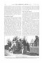
Arc-welded Patches.
R. S. Kennedy, and The British Arc Welding Co., Ltd., No. 8987, dated 16th April, 1912.—When it is desired to weld
two plates together, as for example to cover up a crack, the repair is effected by boring holes at intervals in one or both of the plates, placing them together in the position which they are to occupy, and then joining them permanently by filling up the holes with metal deposited by the electric arc. It is also, of course, desirable to finish off the edges of the patching plate in the same way. Before putting the patch in position, the crack or gap which is to he repaired should be filled with fused metal.
A Pneumatic Shock Absorber.
W. A. P. Werner, No. 7101, dated 22nd March, 1912, Cognate Application No. 8729. dated 12th April. 1912.—This
invention relates to shock absorbers of the kind described in Patent No. 20,389/08, wherein a certain air pressure is kept up in the absorber system. According to this specification, an additional piston and plunger are provided in the shock absorber. By this means the air pressure is kept up by the relative movement of the axles and the body, when the movement would not be such as normally to obtain the necessary pres sure with a single cylinder. The main cylinder and piston are shown at the right-hand side, while the auxiliary cylinder is shown attached to the other side. The piston for the auxiliary is coupled to the axle through a lever at the bottom, so that it moves in opposition to the mair piston. Relative movement of the a ,e and the body in one direction is abs abed by the compression of the air in the main, and in the other direction by air in the small cylinder.
.An Armoured Tire Cover.
L. S. Butler, No. 4479, dated 21st September, 1912.—This specification describes and illustrates an outer cover for a pneumatic tire. It is built up of alternate layers of resilient metal, wire gauze and asbestos. Instead of gauze, thin perforated sheet metal may be used. In the accompanying drawing, from the top of the tread inwards, the successive materials are rubber tread, metal wire gauze, a thin sheet of steel on the tread only, asbestos, three layers of gauze, asbestos, gauze, and a rubber interior.
Cone Transmission Gear.
C. B. Liddell, No. 7878, dated 1st April, 1912.—This specification describes a cheap form of friction transmission gear in which a male cone clutch is mounted on the driving shaft. A corresponding female clutch, of larger size, is mounted on the driven shaft. This latter is arranged to he moved axially for disengaging the clutches, and to be moved along the two shafts to cha_nge the transmission ratio.
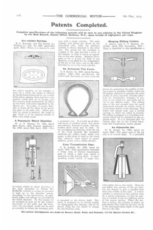
Shaping Milling Cutters.
P. Brown, and F. J. Bostock, No 27,263, dated 27th November, 1912 — There is described in this specification a
device for generating the profiles of mill ing cutters or grinding wheels, which can be readily adjusted to generate the exact profile of cutter required, whereby allowance for interference necessary at present. is not called for, and teeth can be cut -to any desired angle. The cutting edge of the tool extends from the point downwards towards the holder, whith is of the shape shown in the drawings. This holder has turned ends, and a central opening in which the cutter is secured. The cutter is gripped in a swivelling toolcarrier which can be adjusted to any required angle. It is so designed that the cutting edge lies on the central transverse and longitudinal carrier planes.
An Adjustable Jet.
W. E. Muntz, No. 7873, dated 1st April, 1912.—The upper part of the jet tube is of conical shape. It is provided
with radial ribs on the inside, These do not follow the contour of the jet tube, but are shaped to give a parallel bore down the middle of the tube. A hollow cylinder is mounted in this uniform bore by a spring suspension, so that its position is variable under the differing action of the engine suction. When the suction is strong, the cylinder is drawn up and restricts the outlet for the fuel, owing to the decreased radial depth of the gaps between the ribs.