 1
1 2
2 3
3 4
4 5
5 6
6 7
7 8
8 9
9 10
10 11
11 12
12 13
13 14
14 15
15 16
16 17
17 18
18 19
19 20
20 21
21 22
22 23
23 24
24 25
25 26
26 27
27 28
28 29
29 30
30 31
31 32
32 33
33 34
34 35
35 36
36 37
37 38
38 39
39 40
40 41
41 42
42 43
43 44
44 45
45 46
46 47
47 48
48 49
49 50
50 51
51 52
52 53
53 54
54 55
55 56
56 57
57 58
58 59
59 60
60 61
61 62
62 63
63 64
64 65
65 66
66 67
67 68
68 69
69 70
70 71
71 72
72 73
73 74
74 75
75 76
76 77
77 78
78 79
79 80
80 81
81 82
82 83
83 84
84 85
85 86
86 87
87 88
88 89
89 90
90 91
91 92
92 93
93 94
94 95
95 96
96 97
97 98
98 99
99 100
100 101
101 102
102 103
103 104
104 105
105 106
106 107
107 108
108 109
109 110
110 111
111 112
112 113
113 114
114 115
115 116
116 117
117 118
118 119
119 120
120 121
121 122
122 123
123 124
124 125
125 126
126 127
127 128
128 129
129 130
130 131
131 132
132 133
133 134
134 135
135 136
136 137
137 138
138 139
139 140
140 ange of cleaners
Page 87
If you've noticed an error in this article please click here to report it so we can fix it.
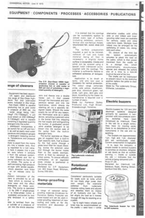
I. Equipment has been appoinUK agent and distributor the range of Dan-Clean highssure hot and cold-water aners. Included in this range, Dan-Clean H600 is capable producing hot or cold water a pressure of 850 psi, the water range being 160/ 2degF (70 /100degC). It will duce steam at 250 /286degF 0 /130degC) and is capable mtraining a regulated quantity ietergent into the outlet.
s, dashboard incorporates a gle switch for on /off and hot/ as well as easily read water Iperature and pressure gauges I a detergent metering control re. Temperature and pressure variable.
Vater is piped from the mains ply into a header tank, flow ig regulated by • a ball valve. -n here it passes into a preter tank where it extracts t from the exhaust system. s then filtered and fed to pump cylinders via two nonrn valves. The pump is of self-lubricating high-pressure on-type with stroke equalizshock absorber tank fitted I an air release valve for ,ing.
onstant lubrication of the iders is provided by an oil feed which is claimed to mize wear and the effect Jetergents on these cornmts. The pump is operated 2 hp 240 V single-phase Dr (a three-phase motor is available) connected by two elts enclosed in a safety d.
'ater is emitted from the p cylinder at a pressure of psi into the shock absorber tank and thence into a double heater coil. It then passes through the thermostat and temperature sensor and into the hand-lance, which directs the cleaning jet via a specially designed nozzle. Should the water supply be cut off for any reason, the thermostat acts as a safety device, actuating a solenoid valve in the burner fuel line, stopping the fuel supply and extinguishing the burner. A graduated control valve enables detergent to be drawn into the suction side of the pump from the built-in detergent tank.
The burner operates on 35sec gas oil supplied from a built-in 2gal capacity tank. Fuel is drawn by the fuel pump through a glass bowl filter for visual checking, across the solenoid valve and through the burner nozzle filter to the nozzle atomizer, which is fired by electrical ignition points. To ensure efficient combustion, an air regulated plate (choke) is positioned in the burner tube.
Marketed by: C.P. Equipment Ltd, Mill Green Road, Mitcham, Surrey CR4 4Xf-1,