


Novel Design for a Rotary Power Unit
Page 36
If you've noticed an error in this article please click here to report it so we can fix it.
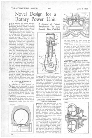
A Resume' of Patent Specifications That Have Recently Been Published
FROIN Phillips and Fowls Aircraft, Ltd., and L. .Heal, both • of The Aerodrome, Reading. comes, in patent No. .S68,67, a design for an engine in' which eccentrics, rolling around a cylindrical bore, play the part of pistons.
In the drawing,' which shows a pair of working units, the two eccentrics (1 and 2) are timed in opposite phase hy external gearing. They both make„ contact with a sliding vane (3), which serves to define the working space. Semi-rotary valves (4 and 5) control the inlet of aii or mixture, and form the combustion chambers. The exhaust leaves via ports leading to a conduit (6).
In the positron shown, the charge in the right-hand chamber has just been fired, and the expansive force is acting to turn the eccentric clockwise. At the same time, the high. pressure is led to. space 7, where it impinges on' the rod of a free piston (8)., which functions as a charging pump. Movement of this to the left blows a charge into the other .valve (4),. in. which it is fired, by spark or compression,and the burning gases are led to the left-hand rotor. The free piston is dofible-actng,, draw
ing in its air via a pair auto-inlet valves (9).
This is' the generalaction as explained in the specification, which does not,: however, , go frilly into. the
details of 'timing. he charging pump appears to be delivering air into the left-hand robir space almost at the end of the power impulse.
A TUBELESS PNEUMATIC TYRE
APNEUMATIC tyre without an inner tube is disclosed in patent No 568,353, by WingfoOt•Corporation, Akron,-. Ohio, Although intended normally to be inflated, the tyre is, nevertheless, fitted with a. runflat" locking band, to prevent creep if deflated.
Referring to the drawing, a standard type of cover is lined, with a layer of soft rubber, which may be left in an unvulcanized, tacky state,the object
being to give it a self-sealing action in the event Lf a small puncture. Surrounding. the rim is a steel, band (1), which can be expanded or 'contracted by a type of buckle joint; the object of This is ease of assembly. The steel band is covered with. a layer of rubber (2), wtrich surrounds the inturried flanges of the band. • The d9taaable side,wali (3) of the rim, When bolted firmly into place, forces the tyre beads into contact with the rubber-faced band and effects a seal which is claimed to be sufficiently air-tight to withstand inflation in the normal manlier.
AMPLIFIED VALVE MOVEMENT FOR TWO-STROKES
PATENT No. 568,002 refers to twostroke engines in which the air charge is admitted at stroke bottom, while the exhaust is discharging from a valve in the head end of the cylinder The patentee is R. Wells, 12, _Avenue South, Surbiton,. Surrey, and he describes a scheme for magnifying the movement of the exhaust valve beyond the usual amount.
The exhaust valve consists tif a piston-like member (I), which moves over ports leading to the exhaust belt (2). The valve is reciprocated, via a short connecting-rod (3), by a rocking shaft which derives its motion from a vertical rod (4). The main subject of the patent is the method of oscillating this rod; an eccentric on the crankshaft rocks an arm (5) pivoted at one end on a stationary pin. The far end drives
the rod, which is thus moved at approximately double the rate 'of the eccentric.
The motion of the •exhaust valve is alsc used to drive the charging pump of the air supply. This pump comprises Co overhead piston (6) connected to the valve by a short rod. The piston works in a short cylinder and delivers air into the belt surrounding 'the inlet ports. The inlet and discharge ports of the pump are controlled by automatic flap-valves (7).
AVOIDING LOW-SPEED DRAG WITH AN HYDRAULIC COUPLING
• T. eliminate drag at idling speeds from an hydraulic coupling of the torque-Converter, type is the main .3bject.: modifications shown in .patent No.' 567,927 by the Hydraulic Brake :Co., Detroit, Michigan, U.S.A. The general structure is on conventional lines, the impeller (I) driving the outpUt. runner (2) by means of transferred fluid. Both members are fitted with radial vanes, hut those on the impeller 'are perforated with 1111MerOUS, small holes, as shown at 3. In• operation at .Jo' 'speeds the:leakage of fluid' through the holes is considerable, because its Row is normal to the perforated faces. 'But, 'as the 'speed . increases, the fluid alter Its/angle of approach until at full speed it follows a path almost parallel with the faces, and does not, therefore, so readily pass through. BY this means, the low-speed slip is .materially increased, without corresponding losses when full power is used,