


SOME MULTI-WHEELE )BLEMS CONSIDERED.
Page 16
Page 17
Page 18
Page 19
If you've noticed an error in this article please click here to report it so we can fix it.
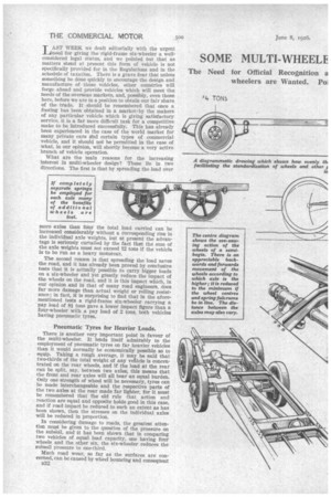
The Need tor Official Recognition a wheelers are Wanted. Po.
Classification of Types. Why. Multimember when Designing. LAST WEEK we dealt editorially with the urgent need for giving the rigid-frame six-wheeler a wellconsidered legal status, and we pointed but that as matters stand at present this form of vehicle is not specifically provided for in the Regulations and in the schedule of taxation. There is a grave fear that unless something be done quickly to encourage the design and manufacture of these vehicles, other countries will forge .ahead and provide vehicles which will meet the needs of the overseas markets, and, possibly, even those here, before we are in a position to obtain our fair share of the trade. It should be remembered that once a footing has been obtained in a market: by the makers of any particular vehicle which is giving satisfactory service, it is a far more difficult task for a competitive make to be introduced successfully. This has already been experienced in the case of the world market for many private cars aind certain tyPes of commercial vehicle, and it should not be permitted in the case of what, in our opinion, will shortly become a very active branch of vehicle operation.
What are the main reasons for the increasing interest in multi-wheeler design? These lie in two directions. The first is that by spreading the load over more axles than four the total load carried can he increased considerably without a corresponding rise in the individual axle weights, but at present the advantage is seriously curtailed by the fact that the sum of the axle weights must not exceed 12 tons if the vehicle is to be run as a heavy motorcar.
The second reason is that spreading the load saves the road, and it has already been proved by conclusive tests that it is actually possible to carry bigger loads on a six-wheeler and yet greatly reduce the impact of the wheels on the road, and it is this impact which, in our opinion and in that of many road engineers, does far more damage than actual weight or rolling resistance; in fact, it is surprising to find that in the aforementioned tests a rigid-frame six-wheeler carrying a pay load of 8i tons gave a lower impact figure than a four-wheeler with a pay load of 2 tons, both vehicles having pneumatic tyres.
Pneumatic Tyres for Heavier Loads.
There is another very important point in favour of the multi-wheeler. It lends itself admirably to the employment of pneumatic tyres on far heavier vehicles than it would normally be economically possible so to equip. Taking a rough average, it may be said that two-thirds of the total weight of any vehicle is concentrated on the rear wheels, and if the load at the rear can be split, say, between two axles, this means that the front and rear axles will all bear an equal burden. Only one strength of wheel will be necessary, tyres can be made interchangeable and the respective parts of the two axles at the rear made far lighter, for it must be remembered that the old rule that action and reaction are equal and opposite holds good in this case, and if road impact be reduced to such an extent as has been shown, then the stresses on the individual axles will be reduced in proportion.
In considering damage to roads, the greatest attention must be given to the question of the pressure on the subsoil, and it has been shown that in comparing two vehicles of equal load capacity, one having four wheels and the other six, the six-wheeler reduces the subsoil pressure to one-third.
Much road wear, so far as the surfaces are concerned, can be caused by wheel bouncing and consequent B32
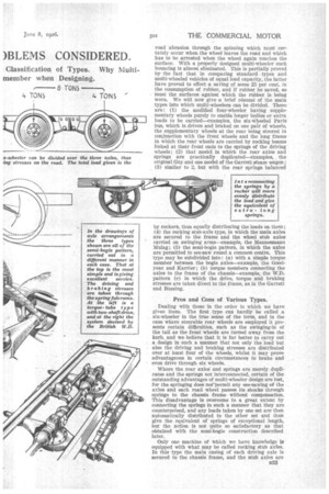
road abrasion through the spinning which must certainly occur when the wheel leaves the road and which has to be arrested when the wheel again touches the surface. With a properly designed multi-wheeler such bouncing is almost eliminated. This is partially proved by the fact that in comparing standard types and multi-wheeled vehicles of equal load capacity, the latter have proved to effect a saving of some 25 per cent. in the consumption of rubber, and if rubber be saved, so must the surfaces against which the rubber is being worn. We will now give a brief resume of the main types into which multi-wheelers can be divided. These are: (1) the modified four-wheeler having supplementary wheels purely to enable longer bodies or extra loads to be carried—examples, the six-wheeled Paris bus, which is driven and braked On one pair Of wheels, the supplementary wheels at the rear being steered in conjunction with the front wheels and the long frame in which the rear wheels are carried by rocking beams linked at their front ends to the springs of the driving wheels; (2) that model in which the rear axles and springs are practically duplicated—examples,, the original Guy and one model of the Garrett steam wagon ; (3) similar to 2, but with the rear springs balanced by rockers, thus equally distributing the loads on them ; (4) the rocking stub-axle ,type, in which the main axles are secured to the frame and the wheel stub axles carried on swinging arms—example, the Mannesmann Mulag; (5) the semi-bogie pattern, in which the axles are permitted to see-saw round a common centre. This type may be subdivided into: (a) with a simple torque member between the bogie axles—example, the Goodyear and Karrier ; (b) torque members connecting the axles to the frame of the chassis—example, the W.D. pattern (c) In which the drive, torque and braking stresses are taken direct to the frame, as in the Garrett and Bussing.
Pros and Cons of Various Types.
Dealing with these in the order in which we have given them. The first type can hardly be called a six-wheeler in the true sense of the term, and in the ease where steerable rear wheels are employed it presents certain difficulties, such as the swinging-in of the tail as the front wheels are turned away from the kerb, and we believe that it is far better to carry out a design in such a manner that not only the load but also the driving and braking stresses are distributed over at least four of the wheels, whilst it may prove advantageous in certain circumstances to brake and even drive through six wheels.
Where the rear axles and springs are merely duplicates and the springs not interconnected, certain of the outstanding advantages of multi-wheeler design are lost, for the springing does norpermit any see-sawing of the axles and each road wheel passes its shocks through springs to the chassis frame without compensation. This disadvantage is overcome to a great extent by connecting the springs in such a manner that they are counterpoised, and any loads taken by one set are then automatically distributed to the other set and thus give the equivalent of springs o,f exceptional length, but the action is not quite so satisfactory as that obtained with the semi-bogie construction described later.
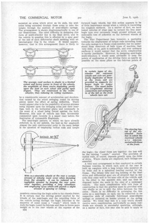
Only one machine of Which we have knowledge is equipped with what may be called rocking stub axles. In this type the main casing of each driving axle is secured to the chassis frame, and the stub axles are mounted on arms which pivot on its ends, the stub axles being extended through these arms to take the weight through the medium of semi-elliptic springs. The arrangement is shown diagrammatically in one of our illustrations. The chief difficulty in designing this form of multi-wheeler lies in the final drive, and in the vehicle in question this is effected by a spur gear at the end of each differential shaft meshing with an internal-gear ring in the wheel. It would appear, however, that in this arrangement there is likely to be a considerable amount of acceleration and deceleration caused by the wheel swinging round its driving .pinion under the effect of spring deflection. There would appear also to be the possibility of severe stresses being imposed upon the swinging arms and their bearings, both in the horizontal plane and torsionally in the event of a wheel being forced against the kerb. However, this type of vehicle has been favourably commented upon recently in a paper read before the Institution of Automobile Engineers.
The semi-bogie pattern, to which we have already referred, is, in our opinion, the best so far employed. Almost the only controversial point in the main design is the question of employing radius rods and torque members connecting the bogie axles to the chassis frame. It is certain that the driving power exerted by the wheels of the semi-bogie and the retarding force of the vehicle acting through the bogie fulcrums in the majority of eases cause a " couple " which tends to rock the bogie round its fulcrum and thus to throw more weight on to the rear wheels at the expense of the B34 forward bogie wheels, but this action appears to be of little importance except when a vehicle is traversing the roughest surfaces. As a matter of fact, we have tested vehicles of what may be termed the free semibogie type over extremely rough ground without any noticeable loss of adhesion on the forward wheels of the bogie.
The War Department has, however, a partiality towards the employment of torque rods extending from the axle casings to a frame cross-member, but we understand from observers of both types of machine that very little, or no, gain is noticeable, and over ordinary surfaces it would appear that the extra complication is hardly justifiable. However, in designing semi-bogie multi-wheelers it would seem advisable to keep the points of application of the driving force as nearly as possible on the same plane as the fulcrum points of the bogie; the closer these are together the less will be the turning " couple " exerted. The provision of radius rods, of course, depends greatly upon the form of drive. Where chains are employed, such fittings are essential.
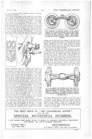
A very neat arrangement is that employed in certain German vehicles, in which each axle at the rear is built up complete with a long torque tube mounted at its front end in a spherical bearing carried by the frame. The torque tube and thg, housing of the final drive and differential gear are 0 situated that in one axle they come well to the near side of the vehicle, and in the other to the opposite side, and can thus be disposed under the seats in the case of a passenger vehicle. The main complication with this form of construction is that the gearbox must be provided with two shafts so as to split the drive between the two axles. There is no difficulty in arranging the two axles as a semi-bogie, as each can be connected to its respective ends of centrally fulcrumed semi-elliptic springs or mounted, on beams pivoted to the spring centres. We think that this is a type which should receive more consideration, particularly as many hundreds are already in successful operation, although, as a matter of fact, this may also be said to apply to
the free semi-bogie pattern, which is used extensively throughout America.
There are many points in the design of a six-wheeler which present difficulties not found in connection with the ordinary type of vehicle. The freedom which must be given to each driving axle in itself is something of a problem, for the axles are seldom in perfect alignment either in the horizontal or vertical plane. Two diagonally opposite wheels of the axles of a bogie may be in potholes whilst the other two may be elevated by humps, and after travelling a few feet the positions of the two axles may be completely reversed so far as theirrocking movement is concerned. At another time both wheels of one axle may be well above those of the other. This makes it essential that the utmost 7 possible flexibility must be afforded the means of driving and any torque or radius rods which may Dc employed, and such rods are usually provided with spherical joints, whilst universal joints of exceptional strength and bearing area are employed in the drive. Chains, when used in such circumstances, show themselves able to withstand these torsional movements to a remarkable degree without jumping their sprockets or causing expessive noise and Wear. Naturally, unless precautions are taken in the design to avoid them, considerable torsional stresses are imposed on the springs, and in. the case of a semi-bogie spring the two ends may be twisted in opposite directions. This can, to an extent, be avoided by locating the axles with suitable radius rods and employing links at -the spring ends; this is the method used in the Trojan six-wheeler, whilst in the Garrett the spring ends rest on slipper pads and are thus practically free. In the W.D. pattern six-wheeler the spring pads on the axle are permitted to rock on spherical seatings, thus avoiding the torsional stresses on the spring leaves.
We have yet to learn of eases of spring breakage with six-wheelers, and where the only connection between axles and chassis frame is through the medium of springs, with the exception of the drive, it might well be that the severing of such a connection would not only put the vehicle out of action, but seriously damage parts other than the springs. For this reason the practice sometimes adopted of employing dual semielliptic springs for the bogie axles appears to possess certain advantages from the point of view of safety. It would certainly prevent an axle from swinging askew in the event of one spring breaking.
Some people with whom we have chatted have found it difficult to understand why the semi-bogie construction should give such smooth running, and this with springs little or no longer than those employed in the ordinary vehicle. The reason is partly due to the fact that the lift or fall of one or a pair of wheels on one axle of a bogie causes only half the lift on the chassis frame which would occur if the springs were secured to the frame at their ends instead of being fulcrumed at their centres. This is also the reason why impact is so greatly reduced, for the energy stored in a falling body is deduced from the formula FS=imv2 where F is the weight of the body and S the height of the fall, so that the energy expended in impact varies directly with the load and as the square of the velocity. From this it can be deduced that the impact of each wheel on a semi-bogie is only a quarter of that which would occur if two ordinary wheels were employed.