


Positive Cylinder Oiling
Page 68
If you've noticed an error in this article please click here to report it so we can fix it.
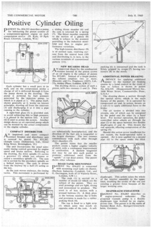
PATENT No. 834,533 describes a pump crowns for lubricating the piston owns of a compression-ignition engine on each compression strae. (D. Kyle, 19 Pp.rk Road. Chiswick, London, W.4.) Each cylinder has a small port in its wall, and on the compression stroke a charge of oil is delivered through it from the pump shown in the drawing. The pump is powered by fuel pressure generated by the injection pump, to which it is piped at 1. The pump itself, shown generally at 2, works on known principles, drawing oil from the reservoir (3) and discharging it at 4 into a pipe running to the cylinder. A sight-feed glass (5) is provided and, to avoid subjecting this to high pressure, it is placed in the suction line. A lever (6) is used to prime the system. Another design shows an air-operated pump which can be worked by the actual compression in the engine cylinder.
COMPACTDISTRIBUTOR
AN improved and more compact contact breaker and distributor unit is covered by patent No. 833,282. (Joseph Lucas (Industries), Ltd., Great King Street, Birmingham, 19.) The unit incorporates the usual automatic timing control governed by engine speed and intake suction. Referring to the drawing, the drive spindle (I) carries a governor (2) which can advance or retard a secondary spindle (3). The cam (4) is carried by the secondary spindle on a helical keyway. The cam is driven from the keyway by a ball' (5) acting as the key. As the cam moves endways, the timing varies. This movement is performed by a sliding thrust member (6) and the cam is returned by a spring (7). The thrust member. responds to the motion of a piston (8) which is subject to the pressure mani fold in the induction and thus to engine per
formance variations.
The high-tension distributor (9)r is of normal type, receiving curent from the central bore (10) and distributing it, in turn, to the various terminals of conventional pattern (II).
NEW RICARDO HEAD
A N improved shape for the combustion "—I recesses located in the piston crown of an oil engine is the subject of patent No. 833,683. Instead of a single pocket, the scheme employs two • or more. (Ricardo and Co. Engineers (1927), Ltd., 27a Ashley Place, London, S.W.1.) The drawing shows a section of such a piston, wilh two recesses (I and 2). They are substantially hemispherical, and the direction of the fuel jets is tangential to the largest diameter. The two recesses communicate with each other through short chamfers (3). The patent states that the .smaller pockets create a higher angular velocity of swirl, with a consequent improvement in combustion. A shallow tangential slot may be cut into each pocket to promote additional swirl from the " squish" at top dead centre. The patent shows other schemes.
ROAD TANK MOUNTINGS
PATENT No. 834,652 is concerned with mounting road tanks on Chassis. (Darham Industries (London), Ltd., and G. Darrington, both of 13 Victoria Street,. London, S.W.1.) The tank (1) is carried o a number n of stools (2) which are the subject of the patent. They are steel pressings and are light, strong no and economical to produce. The stool is of box section with a pressed buttress (3). A thick plate at the bottom receives the U-bolts and provision is made for a rubber packing block (4). The top is fixed to a light strip (5) which joins two stools on opposite sides of the tank. •A soft packing (6) is interposed and the tank is firmly gripped by straps (7) having tensinners (8) in the stools.
ADDITIONAL POWER BRAKING
A DEVICE for applying additional I-1 power to the normal air braking m
syste by a hand control in the event of fade or failure is shown in patent No. 834,339. (Hoppenstand Motors Inc., 1600 Water Street, Conneautville, Penn., U.S.A.)
The drawing shows a section through the special servo, which is the main feature of the patent. It is operated by compressed air and, in action, thrusts on a rod (1) to apply additional force to the brake. The air system is divided into two circuits, one of which can be energized by the pedal and the other by a hand lever. For normal operation,, the pedalcontrolled valve admits air through the pipe (2) to the space between two flexible diaphragms (3 and 4). This thrusts the rod upwards, effecting compression of the spring (5). •
Should this action prove insufficient for any reason, the hand-operated valve is opened. Air is now applied via a second pipe (6) to the space under the thick
diaphragm. This action raises the whole of the interior assembly to the upper limit, doubling the stroke of the rod and creating a greater force because of the larger working area.
DIAPHRAGM EXHAUSTER PATENT No. 834,865 describes an ste engine-powered exhaur. The proposed vacuum pump is a flexible diaphragm type worked by an enginedriven cam. The patent is in the name of Daimler-Benz A.G., Stuttgart-Unterturkheim, Germany.