


AN AUSTIN TRACTOR PLOUGH.
Page 22
If you've noticed an error in this article please click here to report it so we can fix it.
A Résumé of Recently Published Patent Specifications.
By a remarkable coincidence, the two principal patents of those with which we have to 'deal tins week are concerned with the same subject, and have an unusual feature in common: one is British, the other French.
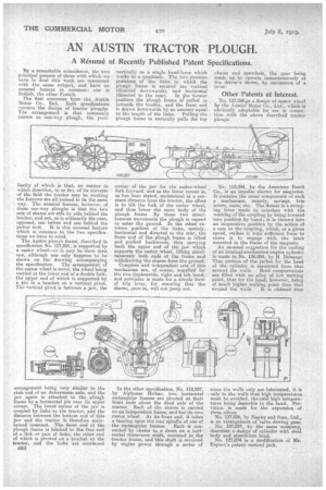
. The first emanates from the Austin Motor Co., Ltd, Both specifications concern the design of tractor iiioughs. The arrangement is that commonly known as one-way plough, the peal
liarity of which is that, no matter in which direction, to or fro, of its traverse of the field the tractor may be working the furrows are all turned to lie the same way. The unusual feature, however, of these one-way ploughs is that the two sets. of shares are side by side behind the tractor, and not, as is ordinarily the ease, opposed, one before and one behind the power unit. It is this unusual feature which is common to the two specifications we have in mind.
The Austin plough frame, described in specification No. 127,091, is supported by a castor wheel—or it may be more than one, although one only happens to be shown on the drawing accompanying the specification. The arrangement of the castor wheel is novel, the wheel being carried at the lower end of a double fork, the upper end of which is supported by a pin in a bracket on a vertical pivot. The vertical pivot is between a jaw, the arrangement being very similar to the stub end of an Ackermann axle, and the jaw again is attached to the plough frame by a horizontal pin near its upper corner. The lower corner of the jaw is coupled by links to the tractor, and the distance between the bottom end of this jaw and the tractor is therefore maintained constant. The front end of the plough frame is hitched to the free end of a link or pair of links, the other end of which is pivoted on a bracket oft the tractor, and the links are continued 050 vertically as a single hand-lever which • works in a quadrant. The two extreme positions of the links to whiCh the plough frame is secured are vertical (directed downwards), and horizontal (directed to the rear). In the former position the plough frame is° pulled in towards the tractor, and the front end is drawn downwards by an amount equal to the length of the links. Pulling the plough frame in naturally pulls the top corner of the jaw for the castor-wheel fork forward, and as the lower corner is, as has been stated, maintained at a constant distance from the tractor, the effect is to tilt the fork of the castor wheel, and thus lower the main body of the plough frame By these two simultaneous movements the plough is caused to enter the ground. ,In the otheA extreme position of the links, namely, horizontal and directed to the rear, the front end of the plough frame is lifted and pushed backwards, thus carrying back the upper end of the jaw which supports the castor wheel, lifting simultaneously both ends of the frame and withdrawing the shares from the ground. Complete and independent sets of this mechanism are, of course, supplied for the two implements, right and left hand, and provision is made for a simple form of trip lever, for ensuring that the shares, once in, will not jump out.
In the other specification, No, 118,287, by Alphonse Hribar, two horizontal rectangular frames are pivoted at their front ends about the dead axle of the tractor. Each of the shares is carried on an independent frame, and has its own castor wheel. At its front end, it takes a bearing upon the rear spindle of one of
the rectangular frames. Each is connected by chains to a drum on a. horizontal transverse shaft, mounted in the tractor frame, and this shaft is revolved by engine power through a series of
chains and Sprockets, the gear being made up to operate instantaneously at the driver's desire, by movement of a. lever.
Other Patents of Interest.
No. 127,0904s a design of castor wheel by the Austin"Motor Co., Ltd., which is obviously adaptable for use in connection with the above described tractor plough: No. 119,444, by the American Bosch Co., is an impulse starter for magnetos. It contains the usual components of such a mechanism, namely, springs, trip levers, cams, etc. The detent is a swinging lever made to interfere with the working of the coupling by being lowered into position by hand ; it is thrown into an inoperative.position by the .action of a cam on the coupling, which, at a given speed, strikes it with sufficient force to cause it to engage with the latch mounted in the frame of the magneto.
An unusual suggestion for the cooling of an internal-combustion engine cylinder is made in No. 126,984, by FL Debauge. That portion of the jacket for the head of the cylihder is separated from that
around tire walls. Both compartments are filled with an alloy of low melting point, that for the head, however, being of much higher melting point than that around the walls. It is claimed that
since the walls only are lubricated, it is only in the walls that high temperatures must. be avoided, the said high temperatures being desirable in the head. Provision is made for the expansion of these alloys.
No. 127,036, by Napier and Sons, Ltd., is an arrangement of valve driving gear.
No. 127,037, by the same company, describes a design of cylinder with steel body and aluminium head.
No. 127,074 is a modification of Mr. Rapson's patent vertical jack.