


Patents Completed.
Page 22
If you've noticed an error in this article please click here to report it so we can fix it.
Wolseley Twin-tire Wheels. Renault Electric Starting Gear. Worm driven Change-speed Gear. An Improved Sparking Plug.
Copies of complete specifications of the patents published on this page can be obtained from the Sales Branch, Patent Office, Holborn, W.C., at the cost of sixpence for each specification.
II. J. V. LEE, No. 13,287, dated 30th May, 1914. This gear operates by using a number of worms of different pitch in conjunction with a gearwheel, the worm_ being selected according to the transmission ratio whieh is required.
In order to accommodate the different worms, the teeth on
the worm-wheel are pivoted. Each tooth has a radial shank rind a, spherical seating surrounding it to engage the rim of the wheel, which is also turned spherical. Each tooth, _further, has a lug projecting sideways, these lugs being -engaged by two retaining rings to hold the tooth in place. A ring is mounted inside the wheel and is engaged with each of the teeth by a pin; so that when one of the teeth is turned by engaging with a different worm, all the teeth are similarly adjusted to the same extent.
THE I.VOLSELEY TOOL ANT) MoToye Can CO., LTD., A. A. REmINGTON, and J. G. SWEENEy, N. 13,640, dated 5th June, 1914. According to this invention the wheel is constructed with a permanently fixed rim or sole-plate which is of the full
width raquirucl for both the tires. It may be made in a single piece of sheet metal or by permanently fixing rigidly together a number of rings or hoops. An abutment-ring is fixed around the middle of the sole-plate to receive the inner beads of the two tires, and the two edges of the sole-plate a 'e grooved to take the detachable rims.
The central abutment-ring may be formed integrally with tl e sole-plate, as illustrated, or it may be formed in two parts, each of which is integral with the grooved part of the rim, a id is secured to a sole-plate.
Various modifications are described and illustrated in the S )ecification.
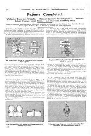
L. RENAULT, No, 15,464, 1914, dated under International Convention 12th July, 1913. The accompanying drawing shows an epicyclie gear for an electric starter. The electric motor on the right-hand 'side at the bottom is coupled to a shaft carrying an eccentric. The sheave, which runs on ball bearings, is constituted by two gearwheels of different size. The larger or right-hand one meshes with a gear fixed on the casing, and the smaller meshes with an internal gear on a. wheel concentric with the motor-shaft. An external gear on this wheel drives the engine-shaft preferably through an idle: gearwheel and a free-wheel clutch. .
This construction gives a very big speed reduction, and is at the same time compact and simple,
W. V. WILLIAMS, No. 14456, dated 12th June, 1914.. Sparking plugs are frequently deteriorated by excessive heatha, resulting from their own resistance losses rather than from the combustion in the cylinder, and it is the object of this invettion to short-circuit the plug automatically when it becomes overheated, A spring steel ring of the shape_ shown in the drawing is mounted on the body of the plug, and held flat by a spring. clip shown on the right-hand side. This Clip is embedded in fusible metal so that when the plug becomes sufficiently overheatedto melt this metal, the,ring is released and Springs up, making contact between the electrode and the outer casing. A special construction of insulator-body is used, -providing an air-space around the central: electrode, withthe object of keeping the latter cool. In a modified arrangement an airdistributor is used to circulate a current of air in Such a
manner as to keep the plug cool. .