


Patents Completed.
Page 22
If you've noticed an error in this article please click here to report it so we can fix it.
Complete specifications of the following patents will be sent to any address in the United Kingdom upon receipt of eightpence per copy at the Sales Branch, Patent Office, Holborn, W.C.
INTERNAL-COMBUSTION ENGINES.—Knight.—No. 12,355, dated 6th June, 1908.—The engine comprises a water-cooled cylinder closed by a watercooled head. An internal extension on the head provides, between it and the cylinder wall, an annular recess. Two internal sleeves reciprocate in this recess. Thesleeves and cylinder are provided with inlet and exhaust ports at the combustion end, the ports being opened and closed by the positive movement of the sleeves. A piston reciprocates inside the sleeves, but does not cover or uncover any of the ports HO that lubricating oil is not forced out. It will be seen that the exhaust. takes place between the water-cooled edges of the cylinder and the cylinder head, and this prevents overheating and distortion of the metal parts.
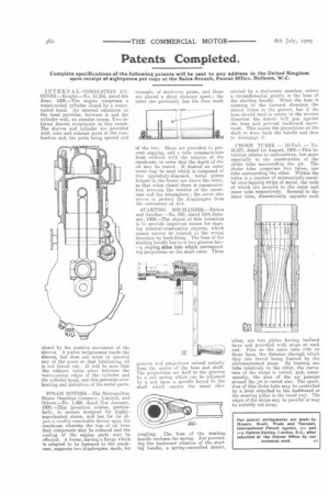
STEAM MOTORS.—The Metropolitan Ste,am Omnibus Company, Limited, and Others.—No. 1,486, dated 21st January, 1909.—This invention relates, particularly, to motors designed for highlysuperheated steam, and has for its object, a readily-removable device upon the crankcase w'hereby the loss of oil from that component may be reduced and the cooling of the engine parts may be effected. A frame, having a flange which is adapted to be fastened to the crankcase, supports two diaphragms, made, for example, of steel-wire gauze, and these are placed a short distance apart ; the outer one preferably has the finer mesh of the two. Stays are provided to prevent sagging, and a tube communicates from without with the interior of the crankcase, in order that the depth of the oil may be tested. If desired an outer cover may be used which is composed of two oppositely-disposed, metal plates hinged to the frame one above the other, so that when closed there is communication between the interior of the crankcase and the atmosphere ; the cover also serves to protect the diaphragms from the settlement of dirt.
STARTING MECHANISM.—Deluce and Another.—No. 842, dated 13th January, 190£1.—The object of this invention is to provide improved means for starting internal-combustion engines, which means cannot be rotated in the wrong direction by back-firing. The boss of the starting handle has in it two grooves hay,Ig sloping sides into which corresponding projections on the shaft enter. These
grooves and projections extend radially from the centre of the boss and shaft. The projections are held in the grooves by a coil spring which can be adjusted by a nut upon a spindle keyed to the shaft which carries the usual claw coupling. The boss of the starting handle encloses the spring. For preventing the backward rotation of the starting handle, a spring-controlled detent, carried by a stationary member, enters a circumferential groove in the boss of the starting handle. When the boss is rotating in the forward direction the detent slides in the groove, but if the boss should tend to rotate in the reverse direction the detent will jam against the boss and prevent backward movement. This causes the projections on the shaft to force back the handle and thus to disengage it.
CHOKE TUBES. — McVail. — No. 16,321, dated 1st August, 1908.—This invention relates to carburetters, but more especially to the construction of the choke tube surrounding the jet. The choke tube comprises two tubes, one tube surrounding the other. Within the tubes is a number of substantially-parallel over-lapping strips of metal, the ends of which are secured to the outer and inner tube respectively. Secured to the inner tube, diametrically opposite each other, are two plates having inclined faces and provided with stops at each end. Pins on the outer tube ride on these faces, the distance through which they can travel being limited by the aforementioned stopa. By turning one tube relatively to the other, the curvature of the strips is varied, and, consequently, the area of the air passage around the jet is varied also. The operation of this choke tube may be controlled by a lever attached to the dashboard or the steering pillar in the usual way. The edges of the strips may be parallel or may be suitably cut away.