 1
1 2
2 3
3 4
4 5
5 6
6 7
7 8
8 9
9 10
10 11
11 12
12 13
13 14
14 15
15 16
16 17
17 18
18 19
19 20
20 21
21 22
22 23
23 24
24 25
25 26
26 27
27 28
28 29
29 30
30 31
31 32
32 33
33 34
34 35
35 36
36 37
37 38
38 39
39 40
40 41
41 42
42 43
43 44
44 45
45 46
46 47
47 48
48 49
49 50
50 51
51 52
52 53
53 54
54 55
55 56
56 57
57 58
58 59
59 60
60 61
61 62
62 63
63 64
64 65
65 66
66 67
67 68
68 69
69 70
70 71
71 72
72 73
73 74
74 75
75 76
76 77
77 78
78 79
79 80
80 81
81 82
82 83
83 84
84 85
85 86
86 87
87 88
88 89
89 90
90 91
91 92
92 93
93 94
94 95
95 96
96 97
97 98
98 99
99 100
100 101
101 102
102 103
103 104
104 105
105 106
106 107
107 108
108 109
109 110
110 111
111 112
112 113
113 114
114 115
115 116
116 117
117 118
118 119
119 120
120 121
121 122
122 123
123 124
124 125
125 126
126 127
127 128
128 129
129 130
130 131
131 132
132 133
133 134
134 135
135 136
136 137
137 138
138 139
139 140
140 141
141 142
142 143
143 144
144 145
145 146
146 147
147 148
148 149
149 150
150 151
151 152
152 An Improved Levelling System DATENT No. 824,150 deals with an
Page 104
If you've noticed an error in this article please click here to report it so we can fix it.
air suspension system and particularly with an air control valve for levelling which prevents continual correction of small changes in attitude and thereby reduces 'air consumption. (Ford Motor Co., Ltd., 88 Regent Street, London, W.I.) The drawing shows the control valve which is actuated by a lever (1). If the lever moves to the right it opens an inlet valve (2) and passes air to the suspension units through an outlet (3). Movement to the left opens an exhaust valve (4) reducing the pressure in the air springs.
The object of the patent is the incorporation of a spring-loaded blow-off valve (5) in the exhaust duct. If the exhaust valve is opened for a small correction, no discharge can occur because the blow-off valve requires a set minimum pressure to open it.
HYDRAULIC STEERING AHYDRAULIC steering system shown in patent No. 824,611 is designed for very heavy vehicles used on and off the road: (Clark Equipment Co., Buchanan, Michigan, U.S.A.)
The drawing is a plan view of the mechanism applied to a steered and driven axle. The steering units consist of a pair of hydraulic cylinders (1 and 2) pivoted on the axle casing. Their piston rods project outwards to pivot on the stub-axle assemblies as shown at 3. The two stub axles are coupled by a normal track rod (4) located on the other side of the axle.
The hydraulic units are interconnected to ensure that they both receive the same pressure. But the forces generated are not the same because when one unit is using the full piston area the area of the other is reduced by the piston rod.
This, however, is in conformity with the degree of loading; the stub axle receiving the greater force needs it because, owing to the geometry of the linkage, it has a
B42 greater moment to overcome. The speciiication includes a geometric diagram to illustrate this point.
GRITTING APPARATUS
PATENT No. 824,424 describes selfcontained grit-spreading apparatus which can be fitted quickly to vehicles with normal-sided bodies to provide fully automatic gritting. (A. Schroder, 35 Gneisenaustrasse, Munich 54, Germany.)
The body of the vehicle is filled with grit and the machine is lowered on to the top of the load. It consists of a frame (1) carrying a conveyor fitted with scoops (2) driven by a small engine (3).
As the conveyor moves, it scrapes away the top surface of the grit, moving it towards the front where a transverse helical screw feeds it to the outlet (4).. The transverse screw is shown at 5. Beneath the outlet is a small rotary spreading disc.
As the grit is used, the conveyor mechanism drops Steadily until it reaches the floor of the vehicle. The spreading rate can be adjusted by a sliding weight (6) which alters the downward force on the conveyor.
IMPROVED HYDRAULIC FLUID
DRAKE fluid described in patent No. .1-) 824,478 is said to be free-flowing, non-corrosive and unaffected by temperatore. The main ingredient is castor oil with a number of additives. (N.V. de Bataafsche Petroleum Maatschappij, The Hague, Holland.)
BIG-END LUBRICATION IMPROVEMENTS in the lubrication of big-end bearings are covered by patent No. 824,204. By cutting grooves in the surface of the bearing, oil can be directed towards the most heavily loaded portion of the shell at the moment of maximum pressure. (The Glacier Metal Co.. Ltd.,
368 Ealing Road, Alperton, Middlesex.)
The drawing shows the lower half of the bearing ring. A wide but shallow, recess (1) starts at the leading edge of the shell and extends for about 45 degrees to terminate in a deep, narrow groove (2).
The bearing receives its oil in the usual way from a crankshaft drilling, the oil being fed into a central groove (3). As most of the upper half of the bearing is plain. the oil flows in semi-timed spurts and ensures that the shallow recess is filled just before the
peak load is applied to the top half. A pair of recesses (4) prevents pressure build-up at the trailing edge of the beating.
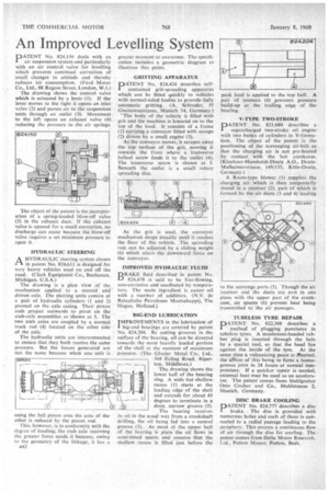
V-TYPE TWO-STROKE
PATENT No. 821,680 describes a supercharged two-stroke oil engine with two banks of cylinders in V-formation. The object of the patent is the positioning of the scavenging air-belt so that the charging air is not pre-heated by contact with the hot crankcase. (Klockner-Humboldt-Deutz A.G., DeutzMulheimerstrasse 149/155, Köln-Deutz, Germany.)
A Roots-type blower (1) supplies the charging air which is then temporarily stored in a receiver (2), part of which is formed by the air ducts (3 and 4) leading to the scavenge ports (5). Though the air receiver and the ducts are cast in one piece with the upper part of the crankcase, air spaces (6) prevent heat being transmitted to the air passages.
TUBELESS TYRE REPAIR
PATENT No. 822,348 describes a method of plugging punctures in tubeless tyres. A mushroom-headed rubber plug is inserted through the hole by a special tool, so that the head lies against the inside of the tyre. At the same time a vulcanizing paste is Aserted, the atition of this being to form a homogenous joint in 24 hours at normal temperature. If a quicker repair is needed, external heat may be used as an accelerator. The patent comes from Stahlgruber Otto Gruber and Co., Mohlstrasse 2, Munich, Germany.
DISC BRAKE COOLING DATENT No. 824,777 describes a disc
brake. The disc is provided with numerous holes and each of these is connected to a radial passage leading to the periphery. This creates a continuous flow of air through the disc for cooling. The patent comes from Delta Motor Research. Ltd., Potton Manor, Potton, Beds.