


Safety Device for Hydraulic Brakes
Page 66
If you've noticed an error in this article please click here to report it so we can fix it.
PATENT No. 699,333 comes from N. Hackett, " Westcourt," 154 Glemayr Avenue, Bondi, New South WaleS, and discloses a safety device for giving emergency braking should the hydraulic pressure fail.
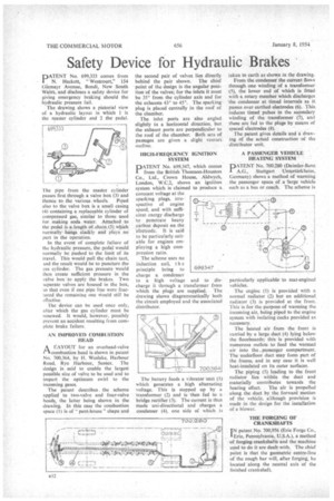
The drawing shows a pictorial view of a hydraulic layout in which 1 is the master cylinder and 2 thepedal.
The pipe from the master cylinder passes first through a valve box (3) and thence to the various wheels. Piped also to the valve box is a small casing (4) containing a replaceable. cylinder of compressed gas, similar to those used for making soda water. Attached to the pedal is a length of chain (5) which normally hangs slackly and plays no part in the operation.
In the event of complete failure of the hydraulic pressure, the pedal would normally be pushed to the limit of its travel. This would pull the chain taut, and the result would be to puncture the gas cylinder. The gas pressure would then create sufficient pressure in the valve box to apply the brakes. Two separate valves are housed in the box, 'so that even if one pipe line were fractured the remaining one would still be effective.
The device can be used once only, after which the gas cylinder must be renewed. It would, however, possibly prevent an accident resulting from corn., plete brake failure.
AN IMPROVED COMBUSTION HEAD
riA LAYOUT for an overhead-valve combustion head is shown in patent No. 700,364, by H. Weslake, Harbour Road, Rye Harbour, Sussex. The design is. said to enable the largest possible size of valve to be used and to impart the optimum swirl to the incoming gases.
The patent describes the scheme applied to two-valve and four-valve heads, the latter being shown in the drawing. In this case the combustion space (1) is of " pent-house " shape and
the second pair of valves lies directly behind the pair shown. The chief point of the design is the angular position of the valves; for the inlets it must be 350 from the cylinder axis and for the exhausts 43° to 453. The sparking plug is placed centrally in the roof of the chamber.
The inlet ports arc also angled slightly in a horizontal direction, but the exhaust ports are perpendicular to the roof of the chamber. Both sets of passages are given a slight venturi outline.
IHGH-FREQUENCY IGNITION SYSTEM
PATENT No. 699,347, which comes from the British Thomson-Houston Co., Ltd., Crown House, Aldwych, London, W.C.2, shows an ignition system which is claimed to produce a
constant voltage at the sparking plugs, irrespective of engine speed, and with sufficient energy discharge to penetrate heavy carbon deposit on the electrode. It is said to be particularly suitable for engines employing a high compression ratio.
The scheme uses no induction coil, t h e principle being to charge a condenser to a high voltage and to discharge it through a transformer from which the plugs are supplied. The drawing shows diagrammatically both the circuit employed and the associated distributor. taken to earth as shown in the drawing.
From the condenser the current flows through one winding of a transformer (5), the lower end of which is fitted with a rotary member which discharges the condenser at timed intervals as it passes over earthed electrodes (6). This induces timed pulses in the secondary winding of the transformer (7), and these are fed to the plugs by means of spaced electrodes (8).
The patent gives details and a drawing of the actual construction of the distributor unit.
A PASSENGER VEHICLE HEATING SYSTEM
PATENT No. 700,280 (Daimler-Benz
• A.G., Stuttgart Untertiirkheim, Germany) shows a method of warming the passenger space of a 'large vehicle such as a bus or coach. The scheme is particularly applicable to rear-engincd vehicles.
The engine (1) is provided with a normal radiator (2) but an additional. radiator (3) is provided at the front. This is for the purpose of warming the incoming air, being piped to the engine system with isolating cocks provided as necessary.
The heated air from the front is carried by a large duct (4) lying below the floorboards; this is provided with numerous outlets to feed the warmed air into the passenger compartment. The underfloor duct may form part of the frame, and in any case it is well heat-insulated on its outer surfaces.
The piping (5) leading to the front radiator lies within the duct and materially contributes towards the heating effect. The air is propelled along the duct by the forward motion of the vehicle, although provision is made in the design for the installation of a blower.
THE FORGING OF CRANKSHAFTS IN patent No. 700,956 (Erie Forge Co., 'Erie, Pennsylvania, U.S.A.), a method of forging crankshafts and the machine used to do it are dealt with. The chief point is that the geometric centre-line of the rough bar will, after forging; be located along the neutral axis of the finished crankshaft.