


SOMETHING NEW IN BRAKE GEARS.
Page 28
If you've noticed an error in this article please click here to report it so we can fix it.
A Résumé' of Recently Published Patents.
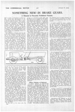
IT is surely a novel. idea to endeavour to control the effectiveness of the brakes by allowing the chassis to move to and fro upoâ ita axles. ,This, nevertheless, is the principle which underlies that brake mechanism which is described in specification No. 189,746, the patentee being F. Porsche. The inventor's principal object is to prevent the wheels from being locked and to eliminate the attendant diffieulties, such as skidding, tyre wear,and, where frontwheel brakes are .eniployeds failure to steer properly.
The -coefficient of friction between. the brake drum and: shoe diminishes, according to this inreritor, as the speed of rotation of the wheel diminishes, so that for a given braking effort, as applied to either the pedal or lever, the tendency to lock the wheels increases as the vehicle speed slaitkens. It is, therefore, essential to reduce the pressure between the shoe and drum as the speed decreases. At present that pressure is; as A rule, maintained constant, and it is obvious, if we accept this statement as to the coefficient of friction, that it should be*rnore than it now is with the vehicle running at high speed, and
should be less than its present usual .value when the vehicle is travelling slowly. An experienced driver makes the necessary allowance himself. The majority, however, do not.
The object of the present invention is to provide a device which will not only adjust the braking effort in accordance with the speed of the vehicle, thus reducing the tendency for the wheels to lock at low speed, but which can also be manually adjusted so as to perform that function equally effectively whatever may be the state of the roads, for, obviously, an adjustment which would prevent wheel-lock when the roads were dry and the adhesion between tyre and road at its best would not do so when the roads were wet or muddy.
The manner of effecting this object is most ingenious,. The chassis is so mounted on its springs that, when circumstances 'arise tending to produce wheel-skid, that is to say, if the brakes are so applied that wheel-skid, in all the circumstances, would 'be most likely to occur, the frame of the vehicle as a whole moves forward on its springs, and, through the medium of a set of links and levers which are coupled to the spring shackles, so modifies the mechanial advantage of the brake pedal or lever as to redues the pressure hetsveen brake shoe and Hum.
In the case of the front axle the c44
.spsitigs are shackled at both; endsiAnd -Vie:front end is coupled to the dunifirea through the medium of a compression spring and a ,daslispot. In the ordinary, way this spring is .sufficiently ;strong to maintain the front.spring in its normal position with respect to the chassis. The adjustment,. however, is such that when the frictional, resistance between wheel and track closely ;approaches the maximum WhiCh 'slip would take place, the spring gives; and the chassis moVas-.beckwards a little with respect to its axle. Now the front-Wheel brakes are, in this particular exaMple, 'appliedby pedal, and the conirection.hetween the pedal and the brake. is a-:floating One, the pin on the brake rod engaging with a slot in the pedal lever, the arrangefnent being such that, in ordinary circumstances, the pin is at the top of the slot and the nearest the fulcrum so that the mechanical advantage of the brake , pedal is at a inaxinaum. The brake rod is held in that position by thehorizonal arm of a bell-crank lever, the vertical arm of which is,coupled by a rod to the front end of the front spring. Consequently, as the chassis moves forward,
this vertical arm of tfie bell-crank lever falls behind, lowering the horizontal arm and carrying the brake rod, and its pm connection to the pedal, lower down in the slot, that is, farther away from the fulcrum, thus reducing the mechanical advantage and decreasing the pressure between brake shoe and drum.
The same effect takes place in connection with the rear brakes, and is brought about by supporting the mounting for the spherical forward end of the combined torque and radius rod in a spring dash-pot.
Other Patents of Interest.
A 'simple method of hydraulically operating a change-speed gear is describedsin specification No. 207,318, by A. J. Stephens. The shaft of the gearbox upon which the sliding gears of an ordinary box would be mounted is hollow and encases a number of passages or pipes, one more in number than the number of wheels. The latter are hollowed and are shaped inside to serve as driven members of friction clutches,. the Iriving pasta of which are keyed upon the shaft and are separated or forced into engagement with the driven parts or closed and disengaged from -.those parts according to the direction of the flew Of oil, which is directed along the pipes or passages to which reference is made. The gearbox embodies a pump
for supplying the oil under press-use, as well as a suitable distributor, by means of which its application may be con
trolled.
•• A , useful gantry or crane, suitable for use on a motor lorry, is described'. by H. Chambers in specification NO. 207,334... There are two standards on , the lorry, mounted, out of the way, near .its, sides. -They support a cross-bar, which carries one end of the beam of . the crane. The other end is upheld by
pairsnf legs which rest on the ground, and which, when the crane is not reiquired, fold up on to the.beam, which 'may' then rest upon the tailboard of the lorry or in some other convenient pos,fthin when it is out of the way.
The clutch which is described in speci-'
fication No. 207,237 by Weller, ia devised to allow a vehicle to overrun its engine when on a down grade. For this purpose a free wheel is embodied in the driven-member 'of the-clutch. This free wheel is normally kept out of action by: a claw clutch, which couples its twe
component parts together. The claw clutch is withdrawn by the initial movement of the clutch pedal.
E. J. Sweetland describes in specification No. 207,212 an apparatus for restoring its effective lubricating qualities to used engine oil. It is designed to be embodied in the power unit of the chassis. The method employed is, firstly, to separate the solids in suspension in the oil by filtration and,. seeondly, to drive off the entrained volatile liquids by heat, preferably the heat of the exhaust gases of the engine. Importance is attached by the inventor to the order in which these two operations are carried out, as he claims that the clarification of the oil leaves it in a condition which is most favourable to efficient distillation.
The carburetter which is described in specification No. 207,217 by J. H. Booth is of the no-jet type. It has a choke tube of porous material, into which the fuel is fed and from which it is drawn by the incoming air as it passes through the tube. The latter is mounted in a, thin metal shell, which is rotatable by means a a Bowden wire or other connection. Slots in the shell register with others in the partition which separates this part of the carburetter from the float chamber, and the rdtation of the shell varies the area available in the slots for the passage of fuel into the porous tube.
Another carburetter is described by F. A. Mills in specification No. 207,220. It is of that type in which the fuel is the first place mixed with a small quari-' tity of air, this rich mixture emerging. through a suitable jet and being subse-2 quently diluted with pure air in accord-, ance with the requirements of the engine.
Specification No. 207,321, by S.H. Attwood and Ruston and Hontisby, Ltd., deleribes a device, which is designed to simplify ignition and throttle control.