


MORE WORKSHOP HINTS.
Page 27
If you've noticed an error in this article please click here to report it so we can fix it.
S0141E USEFUL ideas are embodied in a letter which we have received from " H.H.," of Highgate. Hand drilling, he says, can be made mach easier if the point of the drill be thinned down on the corner of the emery wheel. We presume that he means that the hollow of each spiral of the drill should, near the point, be rested on the emery wheel so as to thin down the strip of metal which joins the two more subatantial parts of the drill together.
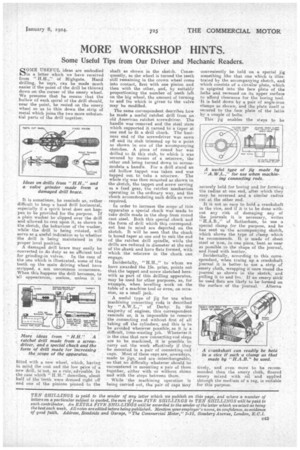
It is sometimes, he reminds us, rather difficult to keep -a hand drill horizontal, especially if a spirit level does not happen to be provided for the purpose. If a plain washer be slipped over the drill and allowed to rest upon it, as shown in the sketch, the behaviour of the washer, while the drill is being rotated, will serve as a useful indication as to whether • the drill is being maintained in its proper level position. A damaged drill brace may easily be • converted to do duty as an efficient tool for grinding-in valves. In the case of the one which is illustrated, some of the teeth (au the main driving wheel have .stripped, a not uncommon occurrence. When this happens the drill becomes, to all appearances, useless, unless it is
fitted with a new wheel, which, having in mind the cost and the low price of a new drill, is hot, as a rule, advisable, In the case. which "H.R." describes, about half of the teeth were dressed right off and one of the pinions pinned to the
shaft as shown in the sketch. Conse
• quently, as the wheel is turned the teeth -still remaining in the crown wheel come into contact, first with one pinion and . then with the other, and, by suitably proportioning the number of teeth left on the big wheel, the amount of turniug to and fro which is given to the valve may be modified.
The same correspondent describes how he made a useful ratchet drill from an old American ratchet screwdriver. The handle was removed and the steel stem which supported it turned to a taper at one end to fit a drill chuck. The business end of the screwdriver was sawn off and its stub trimmed up to a point as shown in one of the accompanying sketches. A piece of round bar was drilled to fit this stub, to which it, was secured by means of a setscrew, the other endbeing turned down to accommodate a handle. For a drill stand an old hollow tappet was taken and was tapped out to take a setscrew. The whole rig was then mounted as shown in the sketch, the tappet and screw serving as a feed gear' the ratchet mechanism
• operating in the ordinary way, and the chuck accomihodating such drills as were required.
In order to increase the scope of this apparatus a special chuck was made to take drills made in the shop from round cast steel. Both this speeial chuck and the form of drill which this correspondent has in mind are depicted on the sketch. It will be seen that the chuck is bored taper at one end to snit the end of the ratchet drill spindle, while the drills are reduced in diameter at, the end of the shank and have flats formed, with which the setscrew in the chuck can engage.
Incidentally, "H.H.," to whom we have awarded the 15s. prize, points out that the tappet and screw sketched herewith as part of this drilling apparatus, may be used for other purposes, as, for example, when levelling work on the table of a machine tool or even, on occasion, as a Small jack.
• A :useful type of jig for use when Machining connecting rode is described by " A.W.L.," of Derby. In the -majority of *engines, this correspondent -reminds us, it is impossible to remove the .connecting rod without first of all taking off the cylinders, and this is to be avoided wherever possible, as it is a difficult, * time-wasting job. Whenever it is the base that new connecting-rod steps -are to be machined, it is possibleto -carry out the work effectively if they -be mounted in u pair of connecting-rod 'caps. Most-of these caps are, nowadays, made to jigs, and • are -interchangeable, -so that no difficulty .whatever should be encountered in mounting a pair of them -together, either withor without shims and with the steps between them.
While the machining operation is being Carried out, the pair of caps May
conveniently be held on a special jig something like that one which is illustrated by the accompanying sketch, and -which consists of a circular plate, which is spigoted into the face plate of the lathe and recessed on its upper surface to afford clearance for the boring tool. -It is held down by a pair of angle-iron clamps as shown, and the plate itself is secured to the face plate of the lathe by a couple of bolts.
. This jig enables the steps to securely held for boring and for forming . the radius at one end, after which they may be reversed and a similar radius cut at the other end.
It is not -so easy to hold a crankshaft in the vice, and if it is to be done without any risk of damaging any of the journals, it is necessary, writes " of Rotherham, to use a special clamp for the purpose, and he has sent us the accompanying sketch, which shows the type of clamp which he recommends. It is made of sheet steel or lion, in one piece, bent as near as possible to the shape of the journal, and lined with leather.
• Incidentally, according to this corre. spondent, when truing up a crankshaft i journal t is betterto use a strip of emery cloth, wrapPing it once round the . journal as shown in the sketch, and pulling it to and fro.' If an emery stick be used flats are likely to be formed on the surface of the journal. Alterna tively, and even more to be recommended than the emery cloth, floured emery mixed with oil and applied through the medium of a rag, is suitable for this purpose.