


HINTS ON MAINTENANCE.
Page 26
If you've noticed an error in this article please click here to report it so we can fix it.
468.—Renewing a Solex Throttle.
It is not often that we deal in these columns with the maintenance and repair of carburetters, but the drawings which accompany this hint deal with a method utilized to overcome the effects of wear on a throttle barrel and body of a Solex carburetter, the wear on which had caused difficulty in starting the engine through the sucking in or an excess supply of air.
The drawings are almost self-descriptive. It will only be necessary to point out that the barrel was resumed and faced, and the body counterbored to take bushes at each side, which were turned to be a running fit on the journals of the throttle barrel in lieu of the rollers previously employed. The sideplates were also refaced and lapped to fit the body. It may be pointed out that it is a simple and inexpensive matter to fit new bushes when the old ones are worn.
469.—An Addition to Hint No. 445.
One of the readers of our " Hints on Maintenance " points out, with regard to Hint No. 445, that it would have been advisable to mention that in all cases the valves should he pet while the boiler is under working pressure. Therefore, the length of the valve liner should be carefully ascertained, as there are two sizes of liners on superheated wagons, viz., 7 ins. and 7R ins., the depth of the 7-in, liner gauge being
in. for the lip. and 5-32-in. for the 1.p. As regards the 7f in. liners, the depth should be 9-16 in. for the h.p. and 11412 in. for the 1.p. Incidentally, the gauges can easily be made from sheet-iron.
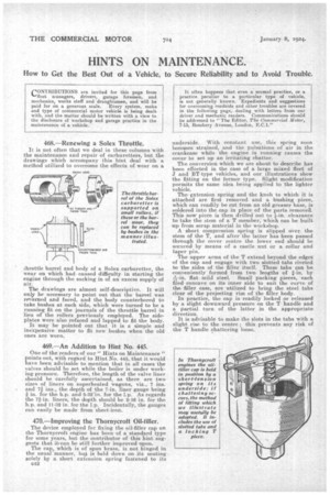
470.—Improving the Thornycroft Oil-filler,
The device employed for fixing the oil-filler cap on the Thornyeroft engine has been of a standard type for some years, but the. contributor of this hint suggests that it. can be still further improved upon.
The cap, which is of spun brass, is not binged in the usuall manner, but is held down on its seating Bolely by a short extension spring fastened to its
c4.2 underside. •With constant use, this spring soon becomes strained, and the pulsations of air in the crankcase while the engine is running causes the cover to set up an irritating chatter.
The conversion which we are about to describe has been effected in the case of a large mixed fleet of and BT-type vehicles, and our illustrations show the fitting on the former type. Slight modification pormits the same idea being applied to the lighter vehicle.
The extension spring and the knob to which it is attached are first removed and a bushing piece, which can readily be cut from an old greaser base, is soldered into the cap in place of the parts removed. This now piece is then drilled out to *-in. clearance to take the stem of a. T member, which can be built up from scrap material in the workshop.
A short compression spring is slipped over, the stem of the T, and after the latter has been passed through the cover centre the lower end should be secured by means of a castle nut or a collar and taper pin.
The upper arms of the T extend beyond the edges of the cap and engage with two slotted tabs riveted to the sides of the filler itself. These tabs can be conveniently formed from twho lengths of fin, by fiat mild steel. Small packing pieces, each filed concave on its inner side to suit the curve of the filler case, are utilized to bring the steel tabs clear of the projecting rim of the filler body.
In practice, the cap is readily locked or released by a slight downward pressure on the T handle and a partial turn of the latter in the appropriate direction. • • It is advisable to make the slag in the tabs with a slight rise to the centre ; this prevents any risk of the T handle chattering loose.