


POINTS IN PRESENT-DAY CHASSIS DESIGN.
Page 19
Page 20
If you've noticed an error in this article please click here to report it so we can fix it.
IN the-course of the past few weeks I have been able to make a very careful study of the chassis 'Which are -offered by aninufaeturers as their 1924 .. models.' They may thus be described, because they are the models that will be current in the ensuing year, even if -commercial chassis manufacturers may consider it good policy carefully to refrain from giving a date to a model, desiring to prevent the idea from gaining currency (as it does in the private car industry) that now models should be expected as each autumn comes round. The impression which I have gained is that the majority of the makers are satisfied that the standard design_ of commercial vehicle chassis does not, in itself, call for much alteration. So long as there is no stagnation of design, this attitude, within strict limits, is a sound one, because here is a large and important class of buyer who are timid and hold up orders until " finality of design " (as if such a thing were possible !) is reached.
A thorough examination of engines and a search-. ing scrutiny of their design go to show that no marked improvement has been introduced recently, although in smalldetails there is evidence that makers are not standing still. ,
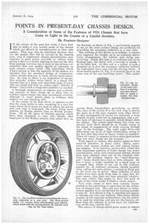
In the matter of the final drive, it appears to me that the worm holds its own, excepting in a very. few cases where bevel gears are used or where the pinion and rack ring is employed, the latter being more popular on foreign models than. on British productions. Of all the types of internal gearing which have been employed in rear axle design, that employed on the Walker electric and, better still, on
the Renault, as shown in Fig. 1, particularly appeals to me as the most perfect design yet produced for _ providing the necessary reduction in a rear axle.
The working of this device is as follows: A tubular axle supports the weight, as in an ordinary sleeveborne arrangement, the tubular axle being nonrevolving. Inside this tube is an ordinary axle of the floating type, but fitted with a bearing to steady it at its outer end. At this end is a pinion of such a diameter as to give the necessary reduction between the high-speed inner axle and the driving wheel. A three-armed spider (A, Fig. 1) is securely fixed to the outer end of the non-revolving sleeve. This spider carries three intermediate gearwheels, as shownThe ratio of the pinion B to the rack ring is exactly the same as if the pair engaged each other direct. In this arrangement all forces are balanced, a large number of gear teeth are in engagement, and a per feet bath of lubricant. is possible, which should make for silence. The pinion shaft being free from any journal load, there should be no trouble owing to the depth of engagement of teeth varying through wear in the bearings. The right angle drive and differential can all be of light construction, owing to the fact that they have no heavy torque to transmit. Taken all round, it appears to have more good points than any other design for the purpose. . .
With regard to brakes, this matter seems to have
received attention in many cases. Servo, pneumatic and vacuum brakes are now almost becoming common. It is, however, curious that, whilst this most important question of brake design was under consideration, costly and complicated systems should have been adopted when one of the simplest solutions of the problem, namely the "more-than-one.pull" brake should have been so little adopted. By this I mean a brake actuated by a hand lever so arranged that, whilst it can act in the ordinary manner for all ordinary purposes, should occasion arise, calling for extra power, a second or third pull on the lever can be given. Many patterns of such brakes have been made from time to time, but, for some reason they have not been generally adopted. The only vehicle that seems to have thiskind of brake is the latest model Yorkshire steam wagon.
Very little seems to have been actually accomplished in the perfecting of apparatus for the utiliza
tion of cheaper fuel. The only new device in carburetters appears to be one devised for burning paraffin or gas oil. It is shown in Fig. 3, and does not appear to embody any very new features. This device merely consists of two separate carburetters—one for petrol, to be used for starting, and one for the heavier oil. Heat from the exhaust is relied upon for vaporization of the less volatile fuel.
The matter of change-speed gears seems to remain very much where it has been all through. The clash gear seems still to hold its own against all comers. It is doubtful to me whether this is an entirely wise pnTiey. The clash gear may be simple and cheap to produce, but it is certainly not the best gear for the purpose that can be produced. Only a small percentage of drivers can manage the changes properly, as one can hear by listening to the horrible_ noise that many drivers make when attempting to change. Even the well-trained drivers of the large omnibus companies often fail to change without damage to the gears. The clash gear is responsible for much of the high cost of upkeep. The six-wheeler, or tractor-vehicle is one of the developments of the year, as many firms seem to recognize the possibilities of the carrying of heavier loads. It is doubtful, however, whether the demand for such a vehicle will be of much value to the manufacturers when split up among so many. There is no doubt a good deal to learn in the successful construction of such a vehicle, and for a time, at least, the pioneers will, in all probability, produce the most successful models. '
Improvements in the methods of suspension are not very much in evidence. Most of the efforts in this
direction seem to have been confined to insulating the body from the chassis, as in the Holden pneumatic device, where air-filled tubes lie between the body and the chassis. In the case of the Strachan device, in which separate leaf springs are fitted at each side of the chassis so as to provide a wide bearing for the body to rest upon, and so minimize any rolling effect, the action of these springs on the road makes riding on solid tyres almost as comfortable as with pneumaties for such vehicles as char-à-bancs and single-decked buses. It is. however, doubtful whether this arrangement would be found successful for double-deckers, on account of the sway. The use of the tipping lorry is growing apace. Hydraulic and electric power are both employed, whilst in a few cases gravity alone is used. Many of the bodies in use to-day seem to be of an unnecessary length, necessitating very heavy mechanism in order to raise them to an angle which will enable them to discharge their load. The economic loading and unloading of goods has not received much attention. Thisseems to be a pity, as much could be done in this direction.
Theimportance of something in the nature of a sprag, 'or device which will effectually prevent a, run away-backwards of either lorry or trailer, does not seem to have received the attention from British firms-which such a desirable adjunct should demand.
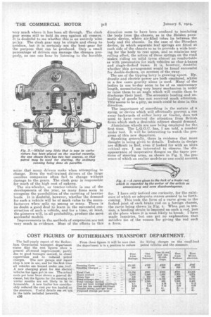
Aluminium wheels are now being employed for the first time. The L.G.O.C. has, I am told, a number under test. It will be interesting to watch the progress of this new departure. Speaking generally, there is evidence that more thought is being given to details. Defects in design are 'difficult to find, even if looked for with an ultra critical eye. I am interested to observe the disappearance of inoperative flanges on the taper portions of steering arms, as shown in Fig. 2, the presence of which on earlier models no one could account
for. I have only noticed one curiosity, for the existence of which no adequate reason seemed to be forthcoming. This took the form of a curve given to the forked joint of each brake rod on a foreign chassis, the curve being shown in Fig. 4. When put in tension, a bending strain is imposed on such a rod, just at the place where it is most likely to break. I have made inquiries, but can get no explanation that satisfies me of the reason for giving the rod such a form.