


Temperature Controls Ignition Advance
Page 62
If you've noticed an error in this article please click here to report it so we can fix it.
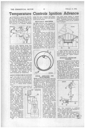
A CCORDING to patent No. 662,174, tithe temperature of an engine is the key factor in deciding the amount of spark-advance, and a scheme for correlating the two is shown in the patent. The patentee. is H. Weslake, Weslake
and Co., Ltd., Harbour Road, Rye Harbour, Sussex. The scheme does not dispense with the usual governor control, but is used as an adjunct thereto.
Referring to the drawing, an aluminium rod (1) is arranged to pass through the exhaust manifold, being firmly fixed at one end (2) but free at the other end so that it can lengthen by heat-expansion. At this end is a magnifying lever (3) which works, via a Bowden cable, an advance-retard lever (4) on the contact breaker.
The arrangement is such that the higher the temperature, the more advanced is the spark. Another scheme shows the same principle using the cooling-water temperature as the controlling factor, whilst another employs a bimetallic strip operated by the under-the-bonnet air temperature.
SAFETY INNER TUBE BY DUNLOP
AN inner tube of the dual-chamber type, intended to prevent total collapse of the tyre in the event of a burst, is shown in patent No. 663,265 by E. Powell, R. Daw and the Dunlop Rubber Co., Ltd., 1, Albany Street, London, N.W.1.
. The drawing shows a cross-section of the tube, which is, in effect, one tube inside another. The inflation valve (1) leads directly to the inner tube, the exterior chamber being filled through a connecting passage (2) which contains a ball valve. Normally, the ball is held off its seating by a small magnetic insert (3); at speed, however, centrifugal force overcomes the magnetic attraction, and the ball moves outwards into its closing position.
The sealing action of the ball is itnperfect, fine grooves being provided across the seat to permit a small. leak. Should a puncture A36 occur, the inner chamber will deflate slowly, so that the driver will become aware of the damage.
HEAVY-DUTY SIDE-TIPPER
ASIDE-TIPPING body intended for use on large two-wheeled trailers of the earth-scraper type is shown in patent No. 663,084 by Athey Products Corporation, Chicago, Illinois, U.S.A. A low centre of gravity is one feature of the design.
The drawing shows an end view of the vehicle. The main frame consists of channel-sectioned members, heavily cross-braced and fitted with brackets (1). The pivots (2) of the tipping body (3) are hinged on these brackets, the bearings being U-shaped. The top of the U-shape can be closed by a cam, so that one pair or the other can he opened according to which side the load is to be tipped. The power is transmitted by hauling cables (not shown) and a chain (4) limits the angle of tip.
POWER ASSISTANCE FOR HAND BRAKES
THE provision,pf power for operating a hand brake is the subject of patent No. 663,107 by Robert Bosch, G.m.b.H., Stuttgart, Germany. The device stores energy in a spring as a precaution against failure of the servo mechanism.
The hand-brake lever is fitted with the normal pawl-release catch (1) and anauxiliary lever (2). The auxiliary lever is connected by a cable (3) to a valve (4) which controls the supply of compressed air to a cylinder (5). The piston of the cylinder is connected to the brakerod (6) and is backed by a spring (7).
By operating the auxiliary lever, air can be used to compress the spring, an action which takes place during brake release. When the brake is applied, the force of the spring is added to the manual effort. This stored energy is available even if the air supply fails: only when brake release is needed would the driver have to make an extra effort, Normally, however, the spring is re-cocked as soon as the auxiliary lever is gripped.
A slight modification from normal is the shape of the teeth (8) on the quadrant; these are square because the brake is held " off " against compression of the spring.
REMOVING CRANKCASE VAPOURS IMPROVED ventilation for the crank' case of an engine is dealt with in patent No. 661,649 (Fiat S.P.A., Turin, Italy). In this scheme the crankcase is completely sealed, except for an inlet and an outlet for filtered air.
Referring to the drawing, air cleaned by the carburetter filter (1) enters the end of pipe 2 and is driven by its velocity to the bottom of the crankcase. The exit pipe (3) is connected to the overhead-valve casing and is led back into the air-stream, so that the vapours are consumed in the cylinders with the fuel. The circulation is produced entirely by the shape and direction o: the two ends of the tubes.
It is claimed that the arrangement is more simple than present known systems and that the degree of efficiency is twice that of a no*il manually operated hand brake. w