 1
1 2
2 3
3 4
4 5
5 6
6 7
7 8
8 9
9 10
10 11
11 12
12 13
13 14
14 15
15 16
16 17
17 18
18 19
19 20
20 21
21 22
22 23
23 24
24 25
25 26
26 27
27 28
28 29
29 30
30 31
31 32
32 33
33 34
34 35
35 36
36 37
37 38
38 39
39 40
40 41
41 42
42 43
43 44
44 45
45 46
46 47
47 48
48 49
49 50
50 51
51 52
52 53
53 54
54 55
55 56
56 57
57 58
58 59
59 60
60 61
61 62
62 63
63 64
64 65
65 66
66 67
67 68
68 69
69 70
70 71
71 72
72 73
73 74
74 75
75 76
76 77
77 78
78 79
79 80
80 81
81 82
82 83
83 84
84 85
85 86
86 87
87 88
88 89
89 90
90 91
91 92
92 93
93 94
94 95
95 96
96 97
97 98
98 99
99 100
100 101
101 102
102 103
103 104
104 105
105 106
106 107
107 108
108 109
109 110
110 111
111 112
112 113
113 114
114 115
115 116
116 117
117 118
118 119
119 120
120 121
121 122
122 123
123 124
124 125
125 126
126 127
127 128
128 129
129 130
130 131
131 132
132 133
133 134
134 135
135 136
136 137
137 138
138 139
139 140
140 141
141 142
142 143
143 144
144 145
145 146
146 147
147 148
148 149
149 150
150 151
151 152
152 153
153 154
154 155
155 156
156 157
157 158
158 159
159 160
160 161
161 162
162 163
163 164
164 165
165 166
166 167
167 168
168 169
169 170
170 171
171 172
172 173
173 174
174 A New Four-wheel-drive Design
Page 132
If you've noticed an error in this article please click here to report it so we can fix it.
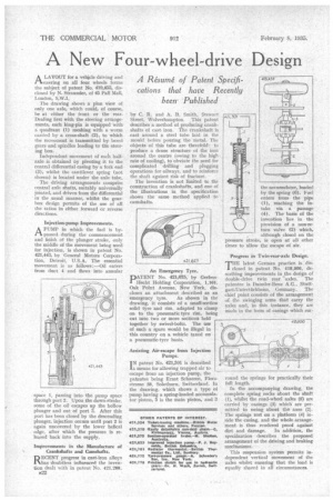
A Résumé of Patent Specifications that have Recently been' Published A LAYOUT for a vehicle driving and Jr1.steering on all four wheels forms the subject of patent No. 419,45'5, disclosed by N. Straussier, of 45 Pall Mall, London, SAVA., The drawing shows a plan view of only one axle, which could, of course, he at either the front or the rear. Dealing first with the steering arrangements, each king-pin is equipped with a quadrant (1) meshing with a worm carried by a cross-shaft (2), to which the movement is transmitted by bevel gears and spindles leading to the steering box.
Independent movement of each halfaxle is obtained by pivoting it to the central differential casing by a fork end (3), whilst the cantilever spring (not shown) is located under the axle tube.
The driving arrangements comprise central axle shafts, suitably universally jointed, and driven from the differential in the usual manner, whilst the gearbox clegn permits of the use of all the ratios in either forward or reverse directions.
Injection-pump Improvements. AA PUMP in which the fuel is bypassed during the commencement and finish of the plunger stroke, only the middle of the movement being used for injection, is shown in patent No. 421,443, by General Motors Corporation, Detroit, U.S.A. The essential movement is as follows:—Oil enters from duct 4 and flows into annular space 1, passing into the pump space through port 2, Upon the down-stroke, some of the oil escapes up the hollow plunger and out of port 3. After this port has been closed by the descending plunger, injection occurs until port 2 is again uncovered by the lower helical edge, after which the pressure is released back into the supply.
Improvements in the Manufacture of Crankshafts and Camshafts.
RECENT progress in cast-iron alloys has doubtless influenced the invention dealt with in patent No. 421,288, u22 by C. R. and A. B. Smith, Stewart Street, Wolverhampton. This patent describes a method of producing crankshafts of cast iron. The crankshaft is cast around a steel tube laid in the mould before pouring the metal. The objects of this tube are threefold: to produce a dense structure of the iron around the centre (owing to the high rate of cooling), to obviate the need for complicated drilling and plugging operations for oilways, and to reinforce the shaft against risk of fracture.
• The invention is not limited to the construction of crankshafts, and one of the illustrations in the specification shows the same method applied to camshafts.
• An Emergency Tyre.
PATENT No. 421,675, by GerbenHecht Holding Corporation, 1,101, Oak Point Avenue, New York, discloses an attachment described as an
emergency tyre. As shown in the drawing, it consists of a small section solid tyre and rim, adapted to clamp on to the pneumatic tyre rim, being cut into two or more sections held together by swivel-bolts. The use of such a spare would be illegal in this country on a vehicle taxed on a pneumatic-tyre basis.
Assisting Air-escape from Injection Pumps.
IN patent No. 421,391 is described a means for allowing trapped air to escape from an injection pump, the patentee being Ernst Schaeren, Florastrasse 38, Solothurn, Switzerland. In the drawing, which shows a type of pump having a spring-loaded accumulator piston, 5 is the main piston, and 3
the accumulator, loaded by the spring (6). Fuel enters from the pipe • (I), reaching the intake via a passage (4). The basin of the invention lies in the provision of a non-return valve (2) which, although dosed on the pressure stroke, is open at all other times to allow the escape of air.
Progress in Twin-rear-aide Design.
77-TE latest German practice is clis1 closed in patent No. 418,806, describing improvements in the design of double-drive twin rear axles. The patentee is Daimler-Benz A.G., Stuttgart-Untertiirkheirn, Germany. The chief point consists of the arrangement of the swinging arms that carry the axles and, in this instance, they are made in the form of casings which sue
round the springs for practica/Ty their full length.
In the accompanying drawing, the complete spring rocks about the shaft (I), whilst the road-wheel axles (5) are carried by casings (3) which are permitted to swing about the axes (2). The springs rest on a platform (4) inside the casing, and the whole arrangement is thus rendered proof against
dirt and damage. In addition, the specification describes the proposed arrangement of the driving and braking mechanisms.
This suspension system permits independent vertical movement cif the axles whilst ensuring that the lead is equally shared in all circumstances.