 1
1 2
2 3
3 4
4 5
5 6
6 7
7 8
8 9
9 10
10 11
11 12
12 13
13 14
14 15
15 16
16 17
17 18
18 19
19 20
20 21
21 22
22 23
23 24
24 25
25 26
26 27
27 28
28 29
29 30
30 31
31 32
32 33
33 34
34 35
35 36
36 37
37 38
38 39
39 40
40 41
41 42
42 43
43 44
44 45
45 46
46 47
47 48
48 49
49 50
50 51
51 52
52 53
53 54
54 55
55 56
56 57
57 58
58 59
59 60
60 61
61 62
62 63
63 64
64 65
65 66
66 67
67 68
68 69
69 70
70 71
71 72
72 73
73 74
74 75
75 76
76 77
77 78
78 79
79 80
80 81
81 82
82 83
83 84
84 85
85 86
86 87
87 88
88 89
89 90
90 91
91 92
92 93
93 94
94 95
95 96
96 97
97 98
98 99
99 100
100 101
101 102
102 103
103 104
104 105
105 106
106 107
107 108
108 109
109 110
110 111
111 112
112 113
113 114
114 115
115 116
116 117
117 118
118 119
119 120
120 121
121 122
122 123
123 124
124 125
125 126
126 127
127 128
128 129
129 130
130 131
131 132
132 133
133 134
134 135
135 136
136 137
137 138
138 139
139 140
140 141
141 142
142 143
143 144
144 145
145 146
146 147
147 148
148 149
149 150
150 151
151 152
152 153
153 154
154 155
155 156
156 157
157 158
158 159
159 160
160 161
161 162
162 163
163 164
164 165
165 166
166 167
167 168
168 169
169 170
170 171
171 172
172 173
173 174
174 The Principle of
Page 108
Page 109
Page 110
If you've noticed an error in this article please click here to report it so we can fix it.
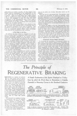
REGENERATIVE BRAKING
A Simple Explanation of the System Employed on Trolleybuses by which the Work Done in Retardation is Usefully Expended in Returning Current to the Overhead Conductors
THERE is a number of methods by which power can he stored, but no apparatus for the purpose is adaptable for use as a portable reservoir in which the energy of a moving vehicle may, as it were, be deposited, when it is desirable that the motion should cease, and subsequently be delivered forth, when the vehicle is to move again. Means for the dissipation of the energy, or for converting it into a form from which it cannot usefully be recovered, are simple, accordingly, in the majority of cases where moving vehicles are concerned, it is more economic thus to waste this kinetic energy.
The alternative to wasting or storing is transference, and if it so happens that a number of vehicles in simultaneous operation be available, and that there be a convenient connection between them all, the momentum of one may be changed to a suitable form of energy and transferred to another to do some of the work of propulsion.
A somewhat similar scheme is found c46 in the inclined railway, where the weight of the descending truck is usefully employed to haul up another, a cable, running around a pulley at the top of the hill, constituting. the connection between them. In this case it is not the momentum, but the potential energy, actually stored in the heavier track, in the process of raising it to an altitude and loading it, that is employed to do useful work.
A type of vehicle which fulfils the conditions outlined above, where both momentum and altitude are considered, is that drawing its motive power from permanent fixed electric conductors, and the tmlleybus is the only form of the type with which this paper is concerned.
In slowing down and in descending hills, it is possible for such a machine to generate electricity which is conveyed to another by the overhead systern and used by it for accelerating, hill-climbing, etc. That, broadly, is the fundamental principle of regenerative braking.
Before proceeding to explain how the principle is applied and to discuss the difficulties involved,it is interesting to record an actual experiment recently made which affords a striking and convincing manifestation of its efficiency. Two machines were driven down a certain hill of considerable length and gradient, regenerative braking being utilized to limit their speed. The current, thus generated, was consumed by a third machine, enabling it, during the descent of the two, itself to climb considerable part of the way up the
same acclivity. No current passed from the main supply to the line during this operation.
A claim made by Guy Motors, Ltd., is that the current generated at one stop--presumably from 25 m.p.h.—will be sufficient to propel another bus 52 ft. up a gradient of Ti in 12.
In any electric motor the armature in rotating creates what is known as counter electromotive force (back E.M.F.). Upon the difference between this and the voltage at which current is supplied to the motor depends the flow of current, which is, of course, roughly proportional to the load. The faster the armature runs, the greater the back E.M.F.
If it come about that, instead of a load, a turning moment is applied to the armature, then the back E.M.F. will exceed the voltage of the supply, and current will flow in the opposite direction. In other words the motor will become a dynamo.
Besides being dependent upon the speed of rotation, however, the back E.M.F. is aho directly proportional to
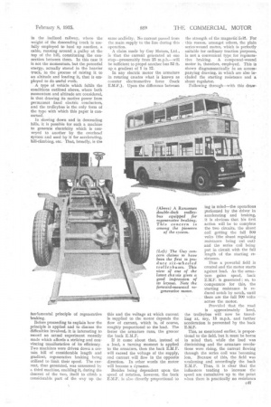
the strength of the magnetic :field. For this reason, amongst others, the plain series-wound motor, which is perfectly suitable for ordinary traction purposes, is not a convenient type. for regenerative braking. A compound-wound motor is, therefore, employed. This is shown diagrammatically in an accompanying drawing, in which are also inchided the starting resistance and a shunt regulator.
Following through—with this draw ing in mind—the operations performed by the driver in accelerating and braking, it is obvious that his first action will be to complete the two circuits, the shunt coil getting the full 500 volts (the shunt regulating resistance being cut out) and the series coil being put in circuit with the full length of the starting resistance.
Thus a powerful field is created and the motor starts against load. As the armature gains speed, back E.M.F. is generated ; so, to compensate for this, the starting resistance is reduced notch by notch, until there are the full 500 volts across the motor.
Provided that the road is approximately level, the trolleybus will now be travelling at, say, 15 m.p.h. and further acceleration is prevented by the back E.M.F.
This, as mentioned earlier, is proportional to the field, but it must be borne in mind that, while the load was diminishing and the armature revolutions were rising, the current flowing through the series coil was becoming less. Because of this, the field was weakening and accordingly the back E.M.F. Thus, it is clear thai: the influences tending to increase the speed are cumulative up to the point when there is practically no resistance
to the vehicle's progress, and back E.M.F. and supply voltage almost balance—as on a slight down grade.
The 500 volts cannot be increased to enable 15 m.p.h. to be exceeded, theredoze the back E.M.F. must be decreased. One means for doing this is to bring into play the shunt field regulator and to put resistances in circuit with the shunt coil step by step, thus reducing the flow of current through it, and effectively weakening the field. In this way the road speed of the vehicle can be brought up to, say, 20 m.p.h.
Another method will be described later, but to avoid confusion, we will continue to consider the simple circuit illustrated, and will now examine what happens when regenerative braking is employed.
Let. us imagine that the vehicle commences to descend a hill, and that the driver wishes to retard its progress. He moves his shunt-regulator control to cut out some of the resistance, thereby strengthening the field, creating a re
tarding force upon the armature and causing the generation of -higher back E.M.F. , This now being greater than 600 volts sends current flowing away to the overhead conductors.
With the fall of speed, he continues to increase the strength of the field by allowing more current to pass through the shunt coil, until all the resistance is out, and the revolutions have fallen to that point where the difference between back E.M,F. and line voltage balances the load created by the descending bus.
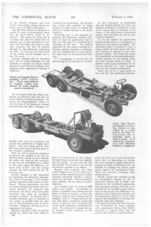
Further braking is still obtainable by employing the rheostatic principle, but, before proceeding to this subject, another important point must he mentioned. During regeneration, the flow of current through the series coil is reversed, therefore the magnetic field created by the shunt coil is materially weakened just when its maximum strength is needed. To obviate this a diverter resistance may be included in the system in parallel -with the field coil, or the last-named may be shortcircuited. Diagrams showing both arrangements are given.
Mention Was Made earlier of another method by which the field Could be c48 weakened in accelerating. The diverter also serves this purpose, it being utilized, in some cases, to control the speed in a similar manner to the shunt regulator.
Referring now to the diagram explaining the rheostatic braking principle, it must be appreciated that in this case the power is absorbed by a resistance on the bus. The current generated by the motor, running as a dynamo, simply traverses a resistance, and the retarding effect is very powerful, right down to low speeds and voltages.
It is interesting to record that its functioning can be arranged to be unaf fected by dewirement of the trolleys, but space does not permit our explaining the system. In any case the bus must finally be brought to rest by the mechanical, vacuum or air brake.
Readers will naturally ask what would happen were all the buses on a certain system simultaneously to brake violently, returning, thereby, a heavy current to the lines. Such an event is most unlikely ; all the same, it is provided for.
Any voltage much in excess of 000 might cause trouble. Accordingly, to protect a machine from burning out its lights or those of another, or from suffering or causing other damage, each is equipped with a voltage-operated device that puts a resistance across the mains to prevent their potential difference from exceeding a predetermined value. The same sort Of apparatus can .be installed, where necessary, at the sub-station.
In this connection, we understand that the English Electric Co., Ltd., has recently developed a system by which direct current may be returned to the source of the high-tension alternating supply when the lines are fed by mercury-arc rectifiers.
As on the matter of regenerative braking itself, there is a divergency of opinion on the system of control. The debatable point is whether to have a single control for both power and electric braking or whether to use independent pedals. The latter, by reason of its similarity to internal-combustionvehicle practice, for one reason, seems the more natural course to adopt. A system of this type is produced by the General Electric Co., Ltd., England, and used on Leyland trolleybuses.
There has to be a brake pedal in 'any case (for the mechanical system), and if the driver were to use his friction brake first, in 'descending an incline, and then attempt to apply regenerative braking he might conceivably make the mistake of running the motor under power against the mechanical brake. There are, hoWever, numerous other considerations.
Finally, against the valuable saving in consumption afforded by the regenerative system, and in brake wear afforded by the combined regenerative and rheostatic systems, there are to he remembered the possibly greater dimensions of the motor, the additional complexity of the wiring and controls, and the precautions that have to be taken against the possibilities of causing dangerously high line voltages.
So great, however, has been the success encountered by buses equipped. with regenerative brakes that despite obstacles, it appears likely that the system will continue to gain headway. .