


SOME FRICTION-DRIVE CHANGE-SPEED GEARS.
Page 30
If you've noticed an error in this article please click here to report it so we can fix it.
A Résumé of Recently Published Patents.
Specification No. 155678, dealing with a frietion-type change-speed gear, with which we have o deal this week, is of considerable interest. The patentee combines a friction gear of the familiar type, in which a driven disc is designed to slide across the face of the driver, with a centrifugal governor. His object is to provide a change-speed-gear which shall be automatic in operation so that, when the speed of the vehicle is low, the gear ratio will be high and vice versa.
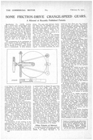
The arrangement of the mechanism is quite simple, as will be gathered by reference to ow' illu.stratian. The driven disc is secured to a long sleeve carried upon a countershaft. A little distance away from it, and driven, by that, same countershaft, is a substantial centrifugal governed.. In the drawing this governor is shown with the weights thrown out to the extreme position, and to correspond, the driven disc is deipcted at the extreme edge of the driver, in the position which provides the lowest ratio. A substantial coil spring is so disposed that it is continuously tending to push the driven disc in towards the centre of the driver, thus increasing the gear ratio. Ae regards details of the construction, there is one to which reference can now conveniently be made. It will be appreciated by all who have had any experience of endeavouring to slide a sleeve upon a shaft, when power is being transmitted by the shaft to the sleeve, that considerable frictional resistance to the sliding movement would be encountered. This inventor sairmonnts the difficulty by substituting, for the driving keys roller bearings. There are slots in the wall of the sleeve and these'bear on rollers carried on pins fixed to the driving shaft.
A description of the working of the apparatus may now be given. It will be appreciated that when about to start a car, and after the engine has been set in motion, the driven disc, acting under the influence of the spring -behind it will have moved in towards the centre of the driver. The gear ratio between engine and beck axle will therefore be a high one, giving the engine the advantage. Since the countershaft is stationary, the governor halls will, of course,. be in
their innermost position. This conespends to what is usually referred to as
the "lowest' gear on a 02..T. .
For a given setting of the throttle valve of the engine, as the -speed of the velhicle increases, the governor weights will tend to move away from the shaft, overcoming the resistance of the spring behind the driven disc, and moving it away from the centre of the driver, thu.s increasing, automatically, the speed of the car as compared with that of the engine. Familiarly expressed, the effect is automatically to change the gear from a "low" to a. "high" one. This will continue until, for the given setting of the throttle valve, equilibrium is established as between the power developed by the engine, and the road resiatanoe, or, alternatively, until the driven disc reaches the outermost edge of the driver, when its further motion will be prevented by the roller "key" coming into contact with the end of the slot-in the sleeve to which the disc is attached.
When the throttle of the engine is partially closed, so that the engine power falls below that necessary to drive the car with the discs in their then position, the car begins to slow down, the governor balls close in, pulling the driven discs near to the centre of the driver and accommodating the gear ratios so that equilibrium between the power developed and the road resistance is once more established. If the contrary effect is experienced as, for example, when, the vehicle commencing to ascend a hill begins to slow down. on account of the increasing resistance, the governor halls will again take effect, with a similar result. The patentee is C. E. Foster.
Other Patents of Interest.
In another friction drive gear, patented by J. M. Rubury in specification No. 155636, the engine eywheel is so
fashioned, that there are two exteerial. cones upon its rear surface. •The cardan shaft is telescopic, and swivels about the rearmost _universal joint. At its front end it carries a steel, clutch member, which has internally-coned surfaces.. An ingenious form of gear-change mechanism is provided, whereby the different internal-cone surfaces and the clutch member can be brought into contact with one or other of those on the flywheel, thus effecting changes of gear ratio. An ingenious design of cylinder head is patented in No. 155694 by Crossley Motors, Ltd. • The patentees draw attention to the fact that trouble is sometimes experienced with loose cylinder heads owing to water leaking past the usual copper and asbestos gaskets. In the Crossley• design communication between water space in the cylinder and that in the head is by a number of cylindrical passages, .and, at the joints, these are sealed by double conical rubber or similar washers, which are eampressed when the joint is made. The usual gasket is &ill employed between cylinder load and cylinder, but it is not now a water, joint. There is actually a space between the edge of this gasket and the rubber water joint so that any water which may leak out will run out of the cylinder instead of inwards.
Specification -No. 155654 has also to do with the design of cylinder heads. The patentee is H. Merton, and the particular feature about this is that the valve sea-tings are not carried in the head, but are formed in the cylinder, so that the head itself can he detached, if desired, without disturbing the valves or their springs. At the mine time, the valves are accessible in the usual manner, without dislurbing the head, by the removal of circular screwed plugs.
M. Birkigt describes in No. 153269 an arrangement of the engine within the bonnet whereby the radiator fan causes a pressure above that of the atmosphere within the bonnet so that, besides drawing coaling air.through the radiator, this fan also serves as a means to provide forced induction,
H. Merton, in No. 155656, describes a method of driving, by the one belt, the radiator fan and circulating water impeller. He claims that his design is advantageous in that it it snore compact than others which have been proposed and which are used. The same patentee describes in No. 155655 a speedometer drive from the gearbox layshafta which, however, appears to involve the latter in being constantly in motion. a-nal revolving 8A a high speed. No. 155673, by F. B. Archer, describes an arrangement of sleeve valve engine in which provision is made for scavenging by a blast of air provided by a fan which drives it into the hollow velve-gearshaft, through a port in that shaft, and thence along passages in the cylinder casting.