


OVERHAULING HALLFORD.
Page 12
Page 13
Page 14
Page 15
If you've noticed an error in this article please click here to report it so we can fix it.
No 9.—The Hanford 3, 4 and 5 Toi The Procedure when Dismantling. ndards for Wear. Dealing with the U
THE HALLFORD is the second chain-driven petrol vehicle to be included in this series of articles, and it presents considerable differences in its main design as compared with the first, embodying as. it does separate casings for the gearbox and countershaft instead of combining these in a unit. This necessitates the use of a. propeller shaft in addition to a clutch shaft. The HaIlford is also provided with very efficient totally-enclosed chain cases, but in spite of these additions it has been so well designed throughout with a viewi to rendering the work of repairing and overhauling as simple as possible that little, if any, extra work is entailed by these differetacea in the design, and many adjustments can be effected by removing cover plates and without otherwise dismantling the various units.
This article covers practically everything in the three heavy models, but not in the 2“onner, which differs radically in its design, and for which space cannot be allotted on this occasion.
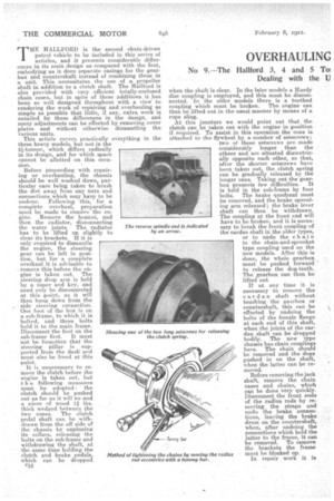
Before proceeding with repairing or overhauling, the chassis should be well washed down, particular care being taken to brush the dirt away from any nuts and connections which may have to be undone. Following this, for a complete overhaul, preparation must be made to remove the engine. Remove the bonnet, and then the radiator, disconnecting the water joints. The radiator has to be lifted up slightly to clear its brackets. If it is only required to dismantle the engine, the steering gear can be left in position, but for a complete overhaul it is advisable to remove this before the engine is taken out. The steering drop arm is held by a taper and key, and need only be disconnected at this point, as it will then hang down from the side steering connection. One foot of the box is on a sub-frame, to which it is bolted, and three bolts hold it to the main frame. Disconnect the foot on the sub-frame first. It must not be forgotten that the steering pillar is supported from the dash' and must also be freed at this point.
It is unnecessary to remove the clutch before the engine is taken out, but t h e following measures must be adopted : the clutch should be pushed out as far as it will eo and a piece of wood 11 ihs. thick wedged between the two cones. The clutch pedal shaft can be withdrawn from the off side of the chassis by unpinning its collars, releasing the bolts on the sub-frame and withdrawing the shaft, at the same time holding the clutch and brake pedals, which can he dropped c12 when the shaft is clear. In the later models a Hardy disc coupling is employed, and this must be disconnected. In the older models there is a toothed coupling which must be broken. The engine can then be lifted out in the usual manner by means of a, rope sling.
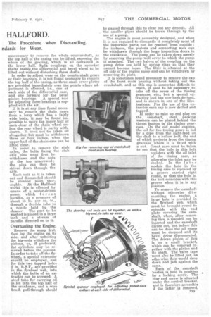
At this juncture we would point out that the clutch can be taken out with the engine in position if required. To assist in this operation the cone is attached to the flywheel by a. number of setscrews; two of these setscrews are made considerably longer than the others and are situated diametrically opposite each other, so that, after the shorter setscrews have been taken out, the dutch spring can be gradually released by the longer ones. Taking out the gear box presents few difficulties. It is held in the sub-frame by four bolts. The brake quadrant must be removed, and the brake operating arm released'; the brake lever shaft can then be withdrawn. The coupling at the front end will have to be broken, and it is neeessary to break the front coupling of the carda,n shaft in the older types, or to undo the chain in the chain-and-sprocket type coupling used on the new models. After this is done, the whole gearbox must be pushed forward to release the dog-teeth. The gearbox can then be lifted out.
If at any time it is necessary to remove the car clan shaft without touching the gearbox or countershaft, this can be effected by undoing the bolts of the female flange at each end of this shaft, when the joints of the carclan shaft can be dropped bodily. The new type chassis has chain couplings here. The chain should be removed and the dogs pushed in on the shaft, when the latter can be removed.
Before removing the jack shaft, remove the chain cases and chains, which can be done very quickly. Disconnect the front ends of the radius rods by removing the straps and undo the brake connections, leaving the brake drum on the countershaft, when, after undoing the connections which hold the latter to the frame, it can be removed. To remove the brackets the frame must be blocked up.
In repair work it is unnecessary to remove the whole countershaft, as the top half of the casing can be lifted, exposing the whole of the gearing, which is all contained in the lower half. Split couplings on the sprocket shafts enable the differential and bevel wheel to be lifted out witheut disturbing these shafts.
If it is at any time found necessary to remove the chain cases from a lorry which has a fairly wide body, it may be found impossible to move the upper half of each clear of the chain wheel unless the rear wheel is partly withdrawn. It need not be taken off altogether, but must be withdrawn three or four inches, when the upper half of the Chain case can be lifted clear.
In order to remove the stub axles, the bolts fixing the stub axle pins must first be withdrawn and the nuts at the top unscrewed ; the pins can then be driven down through the axle.
Each unit as it is taken out and dismantled should be cleaned most thoroughly. At the FIallford works this is effected by means of a motor-driven pump, which forces paraffin, at a pressure. of about 15 lb. per sq. in., through a flexible tube to a nozzle held by the cleaner. The part to be washed is placed in a large tank and a stream of paraffin directed on to it.
Overhauling the Engine.
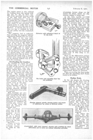
Remove the sump first, then lay the engine on its side, and after unbolting the big-ends withdraw the pistons, or, if preferred, the cylinders may be removed before the pistons. In order to take off the flywheel, a special extractor should be employed, and for this two tapped holes .8in. B.S.F., are provided in the flywheel web, into which the bolts of an extractor can be screwed. A steel tube for carrying oil is let into the top half of the crankcase, and a wire brush pull-through should be passed through this to clear out any deposit. All the smaller pipes should be blown through by the use of a pump.
The engine is most accessibly designed, and when it is not required to dismantle it completely most of the important parts can be reached from outside ; for instance, the pistons and connecting rods can be withdrawn through the large inspection doors in the crankcase. The pump can be taken down merely by removing the pump well cover to which the pump is attached. The two halves of the coupling on the pump drive are held by spring rings so that they cannot become loose. The filter is situated at the off side of the engine sump and can be withdrawn by removing its plate.
It is sometimes found necessary to remove the cap of the front main bearing without taking out the crankshaft, and as this cap is somewhat difficult to reach, it used to be necessary to take off the cover of the timing gearcase, etc., but a special extracting tool has now been devised, and is shown in one of the illustrations. For the use of this extractor each cap is now drilled and tapped. In order to take up end play on the camshaft, steel packing washers can be placed behind the thrust button in the timing gearcase. On the old model engines, the oil for the timing gears is led by a pipe from the sight-feed on the dash to a hollow bolt, the end of which projects from the timing gearcase where it is fitted with a nut. Great care must be taken to see that the hole in this bolt registers wjth the oil inlet of the timing case, as otherwise the inlet may be choked. In the later models the hole in the timing ease is replaced by a groove carried right round, so that the hole in the bolt. coincides with this groove when it is in any position.
To remove the camshaftwithout otherwise d i smantling the engine, a large hole is provided in the flywheel web, which must be brought round to coincide with the end plate covering the em ir-shaft, when, after removing this, a mandril can be inserted and the camshaft driven out, but beforethis can be done the oil pump must be dropped and its bevel drive disconnected. The driven pinion of this is on a small bracket, which can be removed together with the pinion and its shaft. The valve taps must also be lifted out. as otherwise they would drop down and jam against the cams.
Each of the camshaft bushes is held in position by a locking screw. The rear end screw is situated under the control bracket, and is therefore accessible if the latter is removed.
The centre screw is also utilized for holding down the spring locking clip for the oil filler cap. The front camshaft bearing being of the ball type does not require a locking screw. It should be noted that the camshaft timing wheel is pegged as well as keyed. This • wheel is also provided with tapped holes in order that it can be withdrawn, as in the case of the flywheel. It should also be noted that one key is utilized for both the fan pulley and the crankshaft pinion.
The magneto bed is radiused, thus allowing the magneto infinite adjustment instead of by one tooth.
The shims of the rear main bearing cannot be removed unless the bolts are knocked right through below the level of the shims, as each of the• latter fits into the recess in a dowel pin at. the side of the bearings, and it cannot be moved sufficiently to clear this recess unless freed from the bolt.
At the bottom of the crankcase is a special sump, into which any impurities from the oil drain. By removing the sump plug a springloaded. valve closes and the sump can be drained without loss of oil from the crankcase.
Overhauling the Gearbox.
TO examine or repair the gear striking rods, it is not necessary to take off the gearbox top as the gearbox extension arm can be lifted, taking these_ rods with it. If the ends of the rods are worn they can be forged out wider and riveted. The springs operating the plunger for locking the gears in position are inclined to stick and occasionally break ; if this happens, the plungers can be rneved into position close to the small round . cover in the gearbox top half, and the broken, springs, can be replaced, or the sticking springs released, through this if the inspection cover is removed.
Ball bearings are provided throughout the gearbox, except for the floating bush for the reverse pinion. To remove or replace this pinion, it is only necessary to withdraw its bearing pin, remove the cover of the sump and drop the pinion through this.
The cardan joint star at the front end of the gearbox main shaft is a press fit on a keyed parallel shaft and must be with * drawn by the use of a cramp.
Where studs would in the ordinarY course, be. held in the cI4
aluminium, bronze plugs are inserted • for these whilst the aluminium easing is being cast.
In the later models provided with chain-and-toothed type couplings, the coupling at the rear end of the gearbox must be removed with the greatest care, as otherwise the toothed dogs may be closed in by the extractor. III order to prevent this, a special extractor should be employed. This has a solid cylindrical block which fits between the dogs whilst the coupling is being withdrawn.
It should be noted that the gearbox has a sump drain plug and spring-loaded valve similar, to those on the crankcase.
If the chain sprockets are worn;
they can be changed so as to present new wearing faces. Wear sometimes occurs on the counter shaft sleeves, due to the radius rod bushes at their outer ends. The sleeves are each provided with a small snug, and they can be turned right over if this snug is repositioned.
Wear on the differential pinions can be taken up by renewing the phosphor-bronze packing washers
at each side. J. and E. Hall, Ltd., keep a record of the washers
fitted, and It is only necessary for the customer to quote the number on the old washer, when new ones slightly thicker can be supplied. The felt washers throughout the countershaft should be renewed. • When re-erecting the foot brake see that the operating shaft floats freely in its hushes.
Radius Rods.
In the old chassis the floating bronze bush at the front end of each radius rod is apt to hammer down the felt cushion washers at each side of it, and rattling then occurs. These felt wash era must •consequently be replaced. In the later types a spherical bush firmly held in the countershaft bracket is employed, and this prevents trouble in this direction. If wear occurs on these bushes, the radius rod strap can be treated in the same way as the strap of the main bearing, sufficient being filed off • its faces to make a snug fit. To adjust the chains, the distance between the centres of the radius rods can be altered by loosening the two eccentric c apa and turning the eccentrics b y means of a tommy bar, care being taken to tighten the straps after this operation and to make certain that the chains are adjusted evenly.
Rattle-at the rear axle is often .caused by wear on the bushes at the rear end of the radius rods. The cure for this is fitting new bushes, but the axle may have .worn slightly oval and, may require re-turning at this point.
Rear Axle and Wheels.
teen the flange of each radius rod -bush and the radiusrod itself are situated two „loose steel washers with bevelled faces. Between these washers are V felt washers, and the whole is wedged together by a sto.ut Coil spring, which causes the.felt Washers to -he •forced out into contact with a continuation of the -wheel hub. To renew these felt washers, the cast-iron bushes must be forced out, care being taken to take out and replace the threaded dowel pin used for lacking each into position.
In oider to adjust the rear wheel for end play, the rilifs are screwed up tight and then Slacked back about one:third turn, or two slots of the nut.
Steering Gear and Connections.
7n. .steering gear steel packing washers of Vaiyint. Widths can be used at eacli side of the .aeginent for centring this in relation to the worm The ball thrust washers may require renewal, also the phosphor-bronze washers. In the older models the flange of the bracket at the top of the body for carrying the steering tube should he examined for cracks. •
Ball joints are employed for the side connecting rod and tie rod. The brasses of this can be let to
ge-ther, as with a big-end. If the steel halls are worn, their pins can be turned round 90 degrees in order to expose fresh wearing faces, as, naturally
they wear on two sides only. • Some Hallfords are provided with Butler built-up front axles ; these should be examined most Care 'fully and any loose rivets knocked out and replaced by new.
•
Adjusting Hand Brake.
The hand brake shoos are, of the metal-to-metal_ type, requiring no linings. They wear for a considerable time, but when worn beyond the limits allowed for by the adjustments provided, they must lie replaced. The first adjustment should be made at the rear ends of the brake-operating rods, and when the limit is reached on these, the nuts should be slacked back, the cam-operating level unbolted from its quadrant, and bolted on again in the alternative position provided by a second set of bolt holes. Further adjustment. is then made as before. • After new shoes have, been fitted, the cam-operating lever should he returned to its original position on its quadrant..
General Notes.
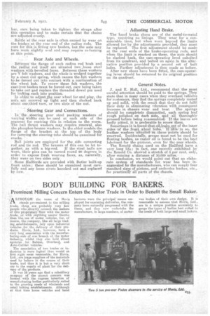
J. and E. • Hall, Ltd., recommend that the most careful attention should be paid to the. springs. They state that in many cases when they overhaul vehicles for eustomers, they 'find the springs completely rusted up and solid, with the result that they do not fulfil their duty in eliminating vibration with consequent increase in chassis wear and tear. The springs should bo completely dismantled, each spring leaf rough polished on each side, and all thoroughly greased before being reassembled. If the leaves are badly pitted, it is preferable to renew them. Sometimes it is found that oil leaks out of the inner sides of the front wheel hubs. If thiis so, the leather washers -situritedjat. the.se points should be renewed. Incidentally, grease must not be used for floating bushes, as -castor oil is found to be the best lubricant for the purpose, even for the rear .wheels. The Renold chains used on the Haillferd have a very long life: in fact, one recently exhibited by the Renold CO. showed a stretch of 3 per cent. only, after running a distance Of 30,600 miles. In conclusion, we would point out that an elaborate system of standards for wear has been inaugurated by the manufacturers, who can simply four standsird sizes of pistons, and undersize bushes, etc.. for practicall:y all parts of the cha.ssis.