


With Intent to Improve.
Page 24
If you've noticed an error in this article please click here to report it so we can fix it.
A Weekly Summary of Recent Patents, of Interest to the Maker and User of Commercial Motor Vehicles.
Selected and Abridged by H. S. Hall, A.M.I.A,E.
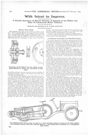
Albin' s Disc Clutch.
Fop; simplicity that type of disc clutch. in which a steel. drive drlisc is gripped between two rings of Ferodo or similar material runs the plain fibre, or leather-lined cone clutch very clok-JOn the score of durability, particularly where it is subject to more than the ordinary amount of rough usage, a disc clutch has the advantage. It has ens or two minor
drawbacks, perhaps, the most important being the liability of the disc and rings to cling to one another, the result being difficulty in changing gear. A recent patent, No. 103,041, by the Albion Motor Car Co., Ltd., has for its object the elimination of this fault and the improvement of this type of clutch in general. This clinging of the discs to the rings, or the tardy release of the clutch, is prevented by including in its construction a light spring which is opposed to the spring or siirings causing engagement. An ingeniously-arranged friction device corrects the tendency of the driven disc to move too far from its driving poeition and tends to maintain it when 'out of engagement in a central position between the two free rings. Reference to our drawing will show that upon the spigot end of the crankshaft are mounted two sleeves, collase-d internally and externally, and that enclosed between the two collars is a light Coil spring. One of these collars is positiVely coupled to the driven disc, the other bears against the flywheel, or stationary part of the dutch. Thie spring therefore operates to separate the discs after release of the clutch-engagement springs. The frictional device takes the form of small springoperated plungers carried in holes in the outer sleeve and bearing upon the circumference of the inner one. A detail of the construction concerning the detachment between the movable driving disc and the fixed driving disc also forms a part of this seine patent.
A Combined Caterpillar and Wheeled Tractor.
The recent accession of interest in agrimotors has had the usual effect of directing the attention of inventors to the wide field which this department of industry offers for the exercise of ingenuity in designing new schemes or improving upon existing ones. The success of the Caterpillar-type of propulsive mechanism as exemplified in the war area, has attracted special notice to this form of construction.
Specifisation No. 100.436 of 1916, just completed, the patentee being the Bulidey-Rider Tractor Corporation, of 1801, Main Street, Los Angeles, California, is an attempt to combine the speed and convenience on roads of the ordinary 'wheeled vehicle with the special capabilities of the Caterpillartype tractor on soft ground. It has, moreover, other features of interest.
The vehicle is provided with three axles, a front one of the normal type with Ackerman steering; the rear one is a dead axle, the wheels being chain driven; the centre axle is carried . by tworadius rods attached at their mar ends to the main,
driving axle, and carried at their front ends by blacks which can be elevated or lowered through the medium of a screwed
gearing. The wheels on the central axle are coupled to those
on the rear axle lmy chains on which are mounted plates forming a type of chain track. This chain track and the chain
wheels are so disposed that the track itself is at a distance of 4 in. or 5 in. inside the circumference of its corresponding road wheel. • By means of claw clutches it is possible to
arrange that this chain track be driven by the rear wheels, or, alternatively, that the rear wheels may run idly within it, the track itself remaining stationary.
There are four methods of working with this tractor. It may either be used as a four-wheel machine, with the central axle lifted and chain tracks not working. On rough ground, or on ground which affords less than the usual tractive grip, the central axle may be lowered until the load is carried by the three axles, the chain track driving gear is then coupled, with the result that the tractive effort on four driving wheels is available instead of only two. Still further depression of the central axle has the effect of elevating the front axle from the ground, throwing the whole weight of the machine on to its two driving axles, giving a still further accession of . what may be termed drawbar effort. In ground which is too soft to allow the use of ordinary road wheels, the machine will ' sink until the chain track takes hold and drives. With the front axle lifted clear of the ground, steering may be accomplished by declutching either chain track at will.