


Patents Completed.
Page 20
If you've noticed an error in this article please click here to report it so we can fix it.
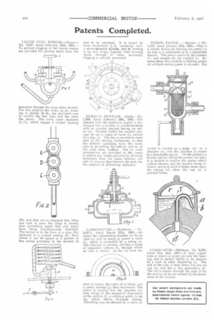
LIQUID FUEL BURNER,—Shave.— No. 3,427, dated February 18th, 1905.— To prevent clogging of the burner means are provided for passing steam from the generator through the same when desired. For this purpose the cocks (A, A), working in glands (II, B), are provided—one to control the fueI inlet and the other the steam. The cocks carry segments (C, C), which engage a central opening
{D), and they are so disposed that when one cock is open the other is closed, thus preventing liquid fuel and steam from being simultaneously admitted_ The burner is in the form of a cone (n), mounted in a conical seating (F), from which it can be raised to a greater or less extent according to the amount of fuel. to be admitted. It is raised by lever mechanism (.1, I), operating upon a screw-threaded spindle, and by moving it up and down, together with blowing steam through it when necessary, clogging is entirely prevented.
EXHAUST MUFFLER.—Ilardy.—No. 2,90t1, dated February 13th, 1905.—The exhaust from the explosion engine is die. charged into a conduit (c) communicating with an annular passage having an outlet (d). Situated within the annular passage (d) are a series of vanes (/), carried by a disc (1). The disc is secured to some part of the driving mechanism, so that the exhaust operating upon the vanes aids in propelling the vehicle, and is, at the same time, mused. One or more perforations are provided in the vanes to relieve any undue pressure by allowing expansion from the space between one pair of vanes to that between the next, for the purpose of preventing explosion.
CARBURETTER. — Buddicon. — No. 3,071a, dated March 27th, 1905.—Air enters the carburetting chamber (a) by an inlet (c), and in doing so passes a valve (f), which is controlled by a spring (e). The chamber is circular, and has a series of tangential orifices (b), through which air also is drawn. As the air from the inlet (c) enters, the valve (di is lifted, and a petrol passage (g) thus uncovered. The petrol is sprayed into the chamber (a), and, owing to the tangential disposition of the orifices (b), a whirling action is Set up, which effects thorough mixing. Throttling may be effected by a valve (/). PETROL FILTER. — Baynes. — No, 5,127, dated January 25th, 1905.—This is a simple device for filtering the petrol on its way to a carburetter or to a liquid-fuel burner. The petrol enters by the conduit (b), and escapes by the conduit (e). Be. tween these two conduits a filtering pocket (d) of finely-woven gauze is situated. The pocket is carried on a ledge (al) in a chamber (a), and the chamber is closed by a detachable cap (6). On the pocket is a handle (d2) for lifting the pocket out when it is desired to remove the matter which collects therein, and the handle, being resilient, serves to hold it firmly down upon the seating (c‘l) when the cup (e) is screwed home.
LI3 RICATOR.—Miihlrad.—No 9,272, dated May 2nd, 1903.—A bent copper tube (s) enters a socket (d) over the bearing, and is packed lightly in its support by a cork or other stoppering (c). The end of the tube is bent down into the oil cup (a), and has a fine perforation (i). The oil is drawn through the pipe (4 by the suction of the air created by the movement of the journal.