


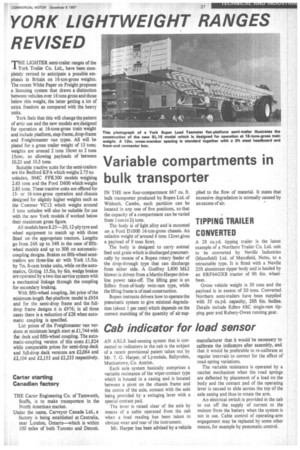
Cab indicator for load sensor
Page 39
If you've noticed an error in this article please click here to report it so we can fix it.
AN AXLE load-sensing system that is connected to indicators in the cab is the subject of a recent provisional patent taken out by Mr. T. G. Harper, of Lynndale, Ballyrobin, Muckamore, Co, Antrim.
Each axle system basically comprises a variable resistance of the wiper-contact type which is housed in a casing and is located between a pivot on the chassis frame and the centre of the axle, contact with the axle being provided by a swinging lever with a special contact pad.
The lever is raised clear of the axle by means of a cable operated from the cab when a load reading has been taken to obviate wear and tear of the instrument.
Mr. Harper has been advised by a vehicle manufacturer that it would be necessary to calibrate the indicators after assembly, and that it would be preferable to re-calibrate at regular intervals to correct for the effect of road-spring variations.
The variable resistance is operated by a ratchet mechanism when the road springs are deflected by placement of a load on the body and the contact pad of the operating lever is caused to slide across the top of the axle casing and thus to rotate the arm.
An electrical switch is provided in the cab to cut off the supply of current to the resistor from the battery when the system is not in use. Cable control of operating-arm engagement may be replaced by some other means, for example by pneumatic control,