


Storing Power from Road Spring Action A SCHEME for making use
Page 62
If you've noticed an error in this article please click here to report it so we can fix it.
of the power absorbed by the suspension system is shown in patent No. 641,367, by M. Navarro and A. Llovet, both of Montevideo, Uruguay.
These inventors show a pneumatic springing system in which the load is carried by compression of air, in a cylinder. The oscillation of the piston caused by road inequalities is used to pump air into a reservoir, from which it can be drawn for braking, tyre inflation and other purposes.,
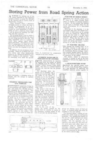
The drawing shows a unit in which 1 is the chassis-carried-portion, the rest of the unit being secured to the axle. The main suspension unit is a• piston (2) which bears against metal bellows above and below. The bellows are kept full of compressed air from the reservoir, and, by adjusting the pressure, the driver can alter the response to suit the load.
In addition, two sets of pistons (3) are provided. These are all fitted with oneway valves, and, when reciprocated, pump air in a"downward direction into pipe 4 leading to the reservoir. Thus, by absorbing work from the up-and down movement, a damping action s created, and the energy is usefully employed.
STEERING MECHANISM FOR I.F.S. VEHICLES
I NDEPENDENT suspension brings its
own problems with respect to steering gear, and patent No. 641,366 shows a gear designed for the purpose. The patentees arc R. Bishop and R. Johnson, Flowton Priory, Harpenden, Hens.
The track-rod in this case is a rectangular-section bar (I) formed from a pair of strips so as to leave a space in between. The bar is connected to the stub-axle arms by small universal joints (2). In operation, the bar is moved by " purnping-in " loose roller (3) into a groove closed by an abutment (4) on the sliding bar. On the end of the steering column is a sprocketlike member (5) which, when turned, imparts motion to the rollers. The rollers really form a chain in which the AVOIDING BACKLASH IN INJECTION-PUMP CONTROL
DETAIL improvements in injection pumps form the subject of patent No. 640,650, from W. Hamill, "Green Gables," Talbot Avenue, Little Aston, Staffs. The aim is to abolish backlash between the rack-rod and the plunger pinions.
The drawings show the pinion (I) in assembly and a section of it on the right. Half the width of the pinion is normal, as at 2, but the upper half (3) is free to revolve on a tubular extension (4) of the lower part. The two parts are joined by a torsion-spring housed in -an internal groove, and assembled with the spring under load.
The action is that the two halves of the pinion exert a nipping effect on the rack teeth, and completely eliminate backlash. The spring loading must, of course, be greater than the maximum operating torque. An alternative scheme applies the same principle to the rack, part of which is slidably spring-loaded with respect to the rest.
As in the case of the pinion, the torque exerted by the ,springs must be suitably in excess of the maximum working torque of the rack to provide the desired action. INJECTOR OF SIMPLE DESIGN
PATENT No. 641,522, which comes from S. A. Andre Citroen, Paris, shows an injector of unusual simplicity in design. In this scheme, the opening of the valve is brought about by the elastic deformation of a thin-walled metal disc.
Referring to the drawing, 1 is the fuel-supply pipe and 2 the needle-valve; the latter is held down on its seating by means of a spring (3). Between the spring and the valve is a thin metal diaphragm (4) which is subject to fuel pressure. When this has risen to the correct value, the diaphragm is lifted against the spring and allows a smaller spring (5) to raise the valve.
AN ELECTRIC HEATER
TOprevent the cooling water of an engine freezing is the aim of a device shown in patent No. 640,679, by H. Greenland, Rowan Cottage, Aldenham Avenue, Radlett. Herts. An advantage of the scheme is that no alterations are necessary to the engine.
The heater, which is electrically warmed, is located in one of the hose connections between the engine and the radiator.
A PILOT-INJECTION PUMP
DATENT No. 641,575 comes from C.A.V., Ltd., Warple Way, London, W.3, and describes an improved and simplified injection pump capable of giving two d'stinct spurts of fuel per cycle. A standard pump can easily be modified to the new scheme.
The drawing shows a section of one pump unit, which works on well-known principles. The modification consists of the use of a small spill-port (1) which co-operates with a bore (2) in the plunger. On the upstroke, fuel is injected in the usual way, but when the Iwo ports pass each other, there is a momentary drop in pressure which interrupts injection. Upon further movement, normal injection is resumed until it is terminated by the uncovering of the helical control edge.