


A Ford Horizontally
Page 36
If you've noticed an error in this article please click here to report it so we can fix it.
Opposed Engine
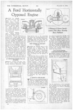
PATENT No. 564,691 conies from the Ford Motor Co., Ltd., 88, Regent Street, London, W.1, and discloses a design for a four-cylindered horizontally opposed engine. Two designs are shown, one being suitable for road vehicles and the other for aircraft; the former is shown herewith.
A one-piece cylinder. block casting extends from one crankshaft centre to the other. The two crankshafts are connected by 'a single large gearwheel forming the output member, herringbone teeth being used ihroughout. An overhead camshaft is employed, with an easily removed inspection cover for accessibility. The starter meshes with the gear of one crankshaft, whilst the dynamo is driven by the other; Attached directly to one end of the camshaft is the ignition distributor. The valve gear, sparking plugs and the usual manifolding are located in a detachable head, which is bolted on to a machined surface running the whole length of the cylinder block. A novel detail is that the camshaft gears -are housed in a close-fitting_ casing and are used • to pump the oil for the lubrication system.
AN IMPROVED PISTON FOR OIL ENGINES
FROM L. Gardner and Sons, Ltd., and others, Barton Hall Engine Works, Patrieroft, Manchester, comes.
in patent No. 564,660, an improved design for an oil-engine piston. According to the patentees, the usual piston, in which the downward -thrust is applied mainly to the ends of the gndgeon-pin, imposes heavy bending stresses to the pin and the piston walls, and the object of the improvement is to avoid this.
The piston is made with a narrow waist portion in whichthe gudgeon-pin is mounted in a pair of solid struts (1). These are of rectangular section, and,
being located close to the connecting rod, reduce the bending stresses to the minimum. They also form a good heatconducting path well away from the rings, whilst some of the heat is dissipated by a set of cooling vanes (2).
NEW DESIGN OF ROTARY VALVE
ATENT No. 564,561 shows a new I design for a rotary valve, the patentee being A. Pomfret, 15, Fir Street, Burnley, Lancs. Advantages claimed for the design are faster possible running, fewer parts, less likelihood of burning and the absence of springs.
Thedrawing shows a section of an air-cooled engine embodying the valve. The rotary member consists of a flat disc (1) provided with ports which, as they revolve, uncover the inlet and exhaust paspages. This disc, which runs in a flanged disc (2) gripped by the cylinder bead, is driven by a train of spur gears Culminating in gear 3. Two sparking plugs are employed, and the piston is provided with cut-away portions (4) adjacent to the plugs. The sealing action during the compression and power strokes is amplified by the pressure acting upwardly on dice 1. The patent covers also the alternative of oscillating the disc instead of rotating it.
• A VEHICLE LIFE-GUARD WHILST they are standard fittings on YV tramcars, lifeguards of the catcher type are not usually fitted to other road vehicles, but there is quite a good case to be made out for them. A design Ltitable for attachment to buses forms
the subject of patent No. 564,688, from R. Farrar, Well Lane Ladder and Truck Works, Winding Road, Halifax.
The device consists of a pair of tubular guides (1) housing sliding rods, to the lower end of which are attached rails (2) and a projecting flexible platform (3). Normally carried in the position shown, it may be released by the driver to fall tothe ground and so prevent any obstacle from passing under the road wheels.
PAY-AS-YOU-ENTER COIN-COLLECTING DEVICE
INTEREST appears to be growing in the pay-as-you-enter system of collecting bus fares, and patent No. 564,578 shows an apparatus for assist
• fog the observation of the conductor as to whether the fare has been paid. The patentee is W. Evans, 7, Waterloo Road, Cardiff. •
The device is illustrated as applied to a double-deck vehicle; two collecting boxes (1) are positioned at points convenient for upstairs and lower-deck passengers. Each box is provided with a small weighted flap upon which the coins fall after insertion; here they rest until a certain number has accumulated, after which they are tipped -into the tube leading to the main box (2). Each box is illuminated; herlding the coins on view for a time enables the conductor to check them.