


Power-clutch Improvements
Page 60
If you've noticed an error in this article please click here to report it so we can fix it.
A R6SUale of Recently Published Patent Specifications AN improved means for controlling power-operated clutches is shown by a well-known concern, Clayton Dowandre Co., Ltd., Lincoln, in patent No. 399,620.
The object of this improvement is the convenient adjustment of the " midway" position of the clutch in such a manner that it can be worked by a small band lever under the control of the driver.
The illustration shows the general principle involved ; the clutch-pedal (3) is operated by a servo-cylinder (1), which is connected to a control valve (4). This valve is worked from the accelerator pedal (25), through a bellcrank, which pivots on a fulcrum pin mounted on a small disc (26). The disc can be turned through a small angle by the hand lever (30).
Thus, whilst the accelerator controls the amount of movement of the valve, the zero position can be altered to suit special conditions. The specification also describes detail improvements in the valve itself.
A New Road-making Material.
LOCAL authorities and others con
cerned with the construction and upkeep of roads will be interested in patent o. 399,624, by Laszlo cl'Antal, Alma-utca, 1, Budapest, Hungary, which describes several new mixtures for use in this connection.
Three formulae are given, typical of the invention, using brown coal-tar as the principal constituent, with the addition of Various other chemicals. The products are claimed to possess plasticelastic balance, tensile strength and thermal elasticity in desirable proportions.
A method of incorporating fibrous matting in the road material is also described.
An Improved Form of Window.
BODYBUILDERS may be interested in patent No. 398,828, by W. H. Bishop, 48, Moor Street, Birmingham, which shows a novel form of window suitable for vehicles. The illustrations depict a form of construction in three consecutive positions; the topmost sketch shows the window closed, and the middle one when it is half-open, whilst the fully open position is illustrated in the lowest.
From these it will be seen that the panel first moves in an outward direction, which is later converted into a forward motion, finally coming to rest in a position alongside the foremost panel, The inventor makes several claims, but omits to suggest what appears to us B46
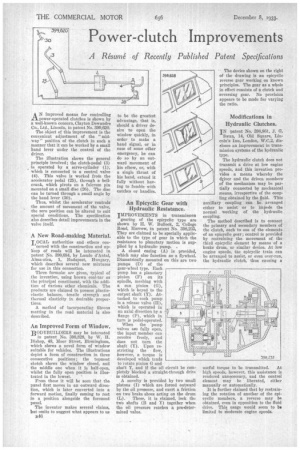
An Epicyclic Gear with Hydraulic Resistance.
IMPROVEMENTS in transmission gearing of the epicyclic type are shown by H. W. Bullock, 2, College Road, Harrow, in patent No. 398,235, They are claimed to be specially applicable to the type of gear in which the resistance to planetary motion is supplied by a hydraulic pump. .
A closed casing (A) is provided, which may also function as a flywheel. Diametrically mounted on this are two pumps (D) of the gear-wheel type. Each pump has a planetary Pinion (F) on its spindle, meshing with a sun pinion (G), which is keyed to the output shaft (1). Attached to each pump is a release valve (H), which is operated in an axial direction by a flange (P), which in turn is pedal-operated.
When the pump valves ape fully open, the input member can revolve freely, and does not turn the shaft (Y). -Upon restricting the flow, however, a torque is developed which tends to rotate pinion G and shaft Y, and if the oil circuit be completely blocked a straight-through drive is obtained.
A novelty is provided by two small pistons (I) which are forced outward by the oil pressure, and exert a friction on two brake shoes acting on the drum (L). These, it is claimed, lock the two shafts (B and Y) together when the oil pressure reaches a pre-determined value. The device shown on the right of the drawing is an epkyclic reverse gear working on known principles. The gear as a whole in effect consists of a clutch and reversing gear. No provision appears to be made for varying the ratio.
Modifications in Hydraulic Clutches.
IN patent No. 398,861, J. G. Swan, 14, Old Square, Lincoin's Inn, London, W.C,2, discloses an improvement in transmission systems of the hydraulic type.
The hydraulic clutch does not transmit a drive at low engine speeds, and this invention provides a means whereby the driver and the driven members• of the mechanism may be partially connected by mechanical means, irrespective of the coupling obtained by the fluid. This auxiliary coupling can be arranged either to assist or to impede the normal working of the hydraulic coupling.
The method described is to connect the primary and secondary members of the clutch, each to one of the elements of an epicyclic gear; control is provided by restraining the movement of the third epicyclie element by means of a brake drum, or similar device. At low engine speeds, the epicyclic train can be arranged to assist, or even over-run, the hydraulic clutch, thus causing a useful torque to be transmitted. At high speeds, however, this assistance is rendered unnecessary, and the control element may be liberated, either manually or automatically.
It is further claimed that by restraining the rotation of another of the epicyclic members, a reverse may be obtained, even in opposition to the fluid drive. This usage would seem to be limited to Moderate engine speeds.