


Patents Completed.
Page 24
If you've noticed an error in this article please click here to report it so we can fix it.
GRINDING MACHINE.—Drunimend. —No. 26,279, dated 12th November, 1909.—This specification describes a small universal grinding machine, iii which the grinding or other cutting tool, and also the headstock carrying the revolving work are each capable of swivelling and of being moved relatively to one
another upon a fixed bed. The main object of the invention is to provide a suitable belt drive without involving the use of any tensioning pulleys, except one to allow of vertical adjustment of the head carrying the grinding tool. A short table projects rearwardly from the main table of the machine, and on it is a tubular stand on which is a cylindrical head capable of vertical movement. In this cylindrical head is fitted a belt. pulley on an axis passing through the axis of the head. A cone pulley on the same axis drives, through a second cone pulley, the shaft on which the grinding tool is fixed. The first belt. pulley inside the head is driven by a belt from the flywheel which passes first over a guide
pulley, then over the tensioning pulley (for vertical adjustment). which is controlled by a spring, and returns by a second guide pulley to the flywheel. The belt is made to pass by these various guide pulleys up into the cylindrical head at a position very close to, if not on, the central axis. This allows the head to be rotated without interfering with the efficiency of the belt drive. In a similar fashion the headstock is driven by a belt from the main flywheel shaft to a counterehaft. On this is fixed a pulley capable of longitudinal motion with the headstock, This pulley drives, by means of a belt, a pulley which can be clutched to the work spindle. The table on which the headstock is fixed is capable of sliding, and swivelling about the sliding pulley. TIRE VALVE—North British Rubber Go., Ltd., A. C. Baker, and A. Johnston.—No. 30,274, dated 28th December, 1909.—This specification describes a valve for pneumatic tires, which serves the double purpose of a valve for inflation and of sounding an alann such as a whistle when the pressure becomes too low, so that the driver of the vehicle may stop before any damage is caused by driving with a deflated tire. An internal screwthreaded sccket forms the junction with the existing valve body et' the ordinary pneinnatic tire. When this socket is screwed honle, it brings the seating of the alarm valve in airtight contact with the interior seating of the existing valve body. The valve for inflating thetire consists of a conical valve of rub ber or other suitable material bedded in a tube, This tube is formed as a piston in a wider tube and is covered at its tipper end with a screw cap-nut. The flange of this tube is held up against the surrounding cylindrical tube by the air pressureinside the tire. A spring is arranged to press the inner tube in the opposite direction. When, therefore. the air pressure falls, Ibis spring will conic into action and will press the inner tube downwards allowieg sir to escape.
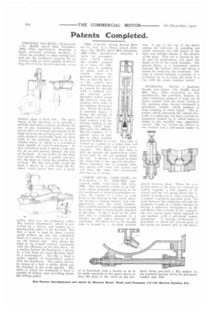
LIOUID LEVEL INDICATOR.—De Dion-Bouton. — No. 9,3381910. date claimed under Convention. 13th July, 1909.--This invention relates to an indicator whose principal application is for the crankcases of internal-combustion engines. It consists of a valve or cock fixed at the bottom of the crank chamber having a vertical channel, and communicating with the crank chamber. This vertical channel is extended upwards by a tube which is hermetically attached to the plug. A cap is fixed on the tube and this is rotatably mounted in a bracket on the upper portion of the crankcase. The sleeve fast on the upright tube is formed as a six-sided member
or is furnished with a handle so as to be easily rotatable in the upper sleeve to turn the plug in the valve at the bot tom. A cap in the top of the sleeve carries the indicator or sounding rod which traverses the full length of the tube and extends almost to the bottom of the plug. This rod is wetted by the oil and on examination will show the depth of oil in the crank chamber. The second figure is a horizontal section through the bottom valve and shows a means for emptying the crankcase. The plug is turned through a portion of a revolution so as to bring the ports in a line with the crank chamber outlet.
SPARKING PLUG. — Boultbee Brooks and Alston.—No. 12,820, dated 26th May, 1910.—According to this specification, the porcelain, steatite or other insulating material is kept out of direct contact with the metal casing of the sparking plug, having interposed a soft-metal washer which protects it from crushing or other injury. The insulator which surrounds the central electrode or conducting rod has a curved enlargement formed on it, which enters a. recess in the metallic case, oppositely curved. The two curves are convex to one another and a soft-metal washer is placed between them. When the ccmponent parts of the plug are screwed up tightly together a line contact is obtained, and the soft metal allows the in sulator to press into it. thus ensuring, it is stated, a perfectly-gas-tight joint. The joint between the conductor rod and the insulator is made in a similar manner by having a spherical enlargement on the rod fitting into a recess in the insulator, the two curves again being opposed to one another, with a soft-metal washer interposed A varying construction is described, in which the curved parts of the joints are formed only in the metal, there being provided a flat surface on the insulator against which the soft-metal washer may bed.