


COMBINED LOADING AND TIPPING GEAR.
Page 32
If you've noticed an error in this article please click here to report it so we can fix it.
A Résumé of Recently Published Patents.
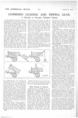
A very ingenious and quite interesting loading device, with which is also combined the function of a tipping gear, is the subject of specification No. 181,836, by H. C. Stone, an American.With the machine described a load may be lifted direct from the ground into the wagon, or it may be moved about over the platform of the wagon. It may be hauled up skids at . the rear of the vehicle, and the body; itself may be unloaded entirely by tipping. The wagon body is hinged to the chassis after the usual fashion of ordinary rearwardly tipping lorries, at a point about two-thirds of the, length of the body, measured from the front. Mounted on the same centre is a substantial U-shaped gantry, which ernbraCes the wagon, as it were, the base of the U, when at rest. in_its...normal.
poiition ;along •the front of thel wagon iiody_ at about the level of the top of its front wall. The legs of the U extend beyond and below the hinge, as is apparent from the accompanying illustrations. There are two cables to each leg of the U, one being ,attached at the extreme end and the other at a point on the other side of the hinge, equidistant from it. These cables are wound, each of a pair, in the opposite direction round drums on a cress-shaft on the chassis, the arrangement of the' drums being such that they all revolve together with the shaft, but are attached to the shaft in a manner which allows of their adjustment from time to time so that'the cable may be kept taut throughout its length. It will be gathered that rotation of the drums, which is effected by gearing from the engine, will swing the gantry in one direction or the other about its pivot..
Another drum on a second cross-shaft, also engine driven, accommodates a cable, which is led round a guide pulley near the pivot of the gantry, along one side of it, and round to the middle of the base of the U, where it falls over a sheave and carries a hook. This is the E48
lifting means for the load. In order to pick up packages from the ground the gantry is Swung over, with 'itstop towards the rear of the lorry, • until the hal< is located over the -load, which is then lifted by means of the loading cable. With the load suspended in this mariner, the gantry is then swung forwarduntil the package is over a convenient spot of 'the platform of the lorry, whefl it is lo ered Off: This Same gantry is also used as a means of tipping the wagon. When this is desired, a vertical spindle, mounted an the front wall of the lorry, is partially rotated. Projecting .fingers on it are by this process .caused simultaneously to release the front end of the body from the Chassis and engageit with the top of the gantry. The latter is then swung over and.taltes the body.,with it. . For .hauling a load, up skids r.at the rear of the body the -hoisting gearis used, the gantry remaining in its normal. position and at rest.
Suitable clutches are, of course, provided, by the aid of which the various! sets of gearing may be caused to operate' or not as is from time to time desired.
Other Patents of Interest.
Sp'e'cification No 169,980, by E. B. Hough, describes still another form of tipping gear. Suitable engine-driven reduction gear, mounted in a gearbox on the chassis, operates a cross-shaft, to which are secured a pair of cam-shaped drums, Curved struts, having flanges which engage the sides of the drum, whereby each drum and its respective strut are kept in alignment, are attached, at their upper ends, to the body, and have, secured to their lower ends, ropes which at their other ends are fastened to the drum, the connection being of such a nature that. drums and struts are • maintained in close engagement one with another by means of the rope. •The arrangement is snch that, as the drum revolves, it lifts the strut, first slowly,
but more quickly As the lift proceeds, moving quite quickly at the last, an pulling up with a jerk -when a projection . on •the drum engages" a notch in the strut. The upper end of the strut is • attached to the under side of the wagon body in the usual manner and tips it
accordingly. -• • • The invention is designed to be applicable to a lorry or to tr trailer, the drive to the gearing in the latter case being effected by means of a flexible shaft, which is fitted at each end with special couplings, capable of quick attachment and detachment from lorry. and trailer. Suitable means of clutching and declutching the gears are provided, and reference is made to a modification which allows of an 'additional degree of tip in 'the case of wagons which are meant habitually to deal with such loads
as wet 'Cori-crate. • • .
'A Phase of the lubrication problem is dealt with in No. 171,408, by C. H. Wills, who describes a method of lubricating hollow overhead camshafts. The object of the inventor appears to be that , of securing an even flow of oil direct to all cams whenever the car is on a hill. An cii pump delivers lubricant under pressure to the middle of the length of the camshaft, which is hollow, and contains two tubes, one at each side of this delivery point, smaller in cross-section than the hole in the camshaft, but eXpanded at each end so as to fit. All .oil, therefore, in travelling to the cam most pass through these tubes to the annular passage between their exterior and the interior of the hole in the camshaft. This passage is effected through a small hole in each tube, so small that neither set of cams (forward or rearward of the pump delivery) may get in over-supply, of oil. Thus, according to the inventor, a proper supply of oil is insured to all the cams, on the surface of which the lubricant is delivered through suitable duets.
The horizontally opposed twin engine gets its meed of attention !this week at the hands raf the Societe Anonyme, des Anciens Etabiissements Hotchkiss et Cie., who, in No. 181,965, describe a construction of engine of this type, their principal object being the simplification of design of th-e power unit and corresponding reduction in manufacturing Cost. Symmetry in the arrangement of the valves and, valve gear is the principal method of achieving this object.
A piece of steel wire with a short branch at right angles at one end, the same being slightly upturned, and a corkscrew handleat the other, composes a tool which.is patented in No. 182,017 by G. Le Blanc-Smith, its object being to facilitate the removal of stone and other fareign Matter 'from between•twin tyres.
An improved arrangement of the ball and socket connection is described by F.. H. Royce in No. 182,043The end of the rod containing the ball end is split, and is' field" together -in the socket pads, an the end ofthe connecting bar itself,•by bolts._The.e.onstruction allows of all slack being quickf and conveniently taken out • without packing. Moreover, the whole Qf the pieces -composing the joint can be tightly flanged together.