


FORD VAN POINTERS.
Page 29
If you've noticed an error in this article please click here to report it so we can fix it.
By R. T. Nicholson (Author of "The Book of the Ford").
AFTER adequate trial, the latest form of Runbaken timer strikes me as being a really good thing. The leading features that brought the Runbaken timer into prominence have been retained but a further improvement has brought it as near to Perfection as would seem to be possible.
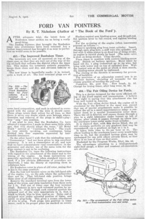
483.—The Improved Runbaken Timer.
The terminals are now all mounted on top of the timer case, so that they are well out of the way of the big oil-bath that suffuses the district where the timer lies. This makes the. terminals entirely accessible, keeps them clean and dry, and obviates liability to shorts.
The new timer is beautifully', made : it is, indeed, quite a work of art. The four terminal plugs are of some hard composition, and each is coloured to corres ond with the colour of the wire it should carry. ose plugs retain their colour for all tune, so that there is never any doubt which wire belongs where. Insertion and removal of the plugs is : they " snip " into position. I am 'glad to note that the Runbaken Co. have adopted a suggestion I made to them some little while ago, that they should adopt the name "All Metal Track" instead of "Continuous Track." The track is,very strictly speaking, not continuous, being divided into four segments separated by hairbreadth insulators.
On the other hand I wish that the misleading name "Commutator had not been given to this excellent accessory. It is not a commutator at all, and now that we have commutators—real commutators—in the generator and starter, use of the same term for the wipe contact is apt to be confusing. The Runbaken Co. issue the following instructions with regard to the attachment of the timer and to the timing of the engine. As these instructions are generally applicable (even when standard timers are used, if a few obvious differences of procedure are observed), I take the liberty of repeating them in substance here.
Fit Runbaken rotor in place of old rotor, seeing that it lies in the same position. Run the four low-tension wires on the left-hand side of the engine, i.e., on the side where the carburetter does not lie. That left-hand aside position brings them clear of all obstructions.
Remove the standard terminal eyes from the lower ends of the wires, and strip insulation from those ends for in. Pull out of timer case the four terminal plugs. Remove in turn each coloured portion by unscrewing it. Push through each coloured portion the stripped end of the wire appropriate to it, that. is black to black, blue to blue, and so on. Splay end of stripped wire under coloured portion of timer, and screw on plug-body. This gives a secure attachment of wire to plug. Push plugs into position in timer cover, each in its proper place (as marked on cover). Slacken control arm binding-screw, and fit pull-rod. Set ignition lever to full retard, and tighten binding screw. . For the re-timing of the engine (often inaccurate) proceed as follows :— Remove sparking plug from front cylinder. Insert, through open plug hole, a stiff wire into eylinder, and feel with it when piston is on dead top of firing stroke, as engine is turned slowly by hand (The inlet valve is shut on firing stroke). Close throttle. Place timer in position with control binding-screw slack. Switch on battery ignition. Move timer by hand till' No. 1 plug (connected up to its wire, but lying with lower end on top of cylinder) fires. With the control arm at the point at which it then stands, the _binding-screw should be tightened. The closing of the throttle is necessary for prevention of backfires.
The provision of an adjustable control arm is an excellent feature, obviating all necessity for the clumsy practice of bending the pull-rod. Complete, 30s. post free. New brush, 2s. 6d. Charge for truing timer, after long wear, 3s. Crd.
484.—The Fair Oiling Device for Fords.
This is a device designed for the more efficient oiling of the Ford engine and transmission. I believe I am right in saying that this attachment also has been well tested in .America.
With the Fair oiling device fitted, the engine oil is circulated by the flywheel in the usual way, except that use of special attachments make it possible to collect the oil in a small supplementary sump—a container fixed tor a special transmission cover door. There the oil is filtered, and passes thence through a pipe to a sight lubricator under bonnet on left of engine, after which it passes through• an elbow into the crankcase lower cover under front cylinder. It is claimed that, with this device fitted, the oil will circulate perfectly on any gradient that may be encounterea—on a gradient as high as 1 in 3.
It takes little time to fit—an hour or so. The elbow leading to the crankcase lower cover would take time to fit, but the standard bottom plate may be exchanged fOr one with elbow already fitted, GO that there is no loss of time on that score.
Marketed by the Progress Works, Rhyl, 52s. 6d. The advantages attaching to a (well-protected) sight-feed gauge, a filter and constant oil-circulation are obvious.