


THE SIX-WHEELER OMNIBUSES OF PARIS.
Page 11
Page 12
If you've noticed an error in this article please click here to report it so we can fix it.
A Technical Description of a Rigid-frame Multi-wheel Vehicle which is Proving Successful in Everyday Passenger Service.
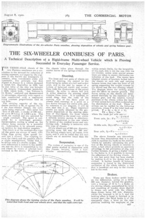
THE THREE-AXLE chassis of the new Parisian omnibuses are a conribution to the demand for reduction of mining expenses, eavisaged by the engiLeers of the Societe des Transports en )(ammo, after considerable study and xperiment.. The principle was first elopted in France in a vehicle designed
Espitallier in 1C05, but he real value of the idea was brought o the fure4 by Commandant Lindecker n 1908, "whose book, "Leg Voitures %A. iix Roues," analysed and demonstrated he advantages, especially with regard to hose constructed with a suspension :iving constant proportionate load on ad]. axle.•
The carrying capacity of the sixeheeler omnibus is 48, as against the .38 f the four-wheeler chassis, the same Agine being employed. This latter has . bore of 105 mm., a stroke of 150 mm., .nd gives 34 b.h.p. at, 1,0Xt r.p.m. The -elves are worked and are operated by single camshaft. The speed is conrolled by a centrifugal goveezior. Chernao-siphon cooling is relied on, the adiator being assisted by a powerful an Lubrication is by pressure pump, he ignition by high-tension magneto. The clutch is of the multiple-disc type ad the gears are always in mesh, with lining doge giving three speeds foreard and a reverse. The coupling be: wean the clutch and the gearbox allows Tr slight misalignment, whilst that to he driven axle is a double cartlan. The evel differential is bolted to the middle xle and the drive is transmitted to the cad wheels by means of internal teeth lachnied in the drums, Propulsion of
the chassis' takes 'place through the master leaves of the springs of the driven axle.
Steering.
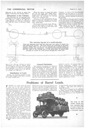
The front and rear pairs of wheels are used for steering, the control to the front being by means of a ball and socket joint, and tothe rear by means of a system of balanced cranks and connections (wide the illustrations of the actual chassis). In order to obtain full lock in either direction the .steering wheel , requires three turns. It is essential, to avoid drag, that the radii of the steering arcs of the three pairs of wheels shall converge at a point on a line drawn through the centre axle, and, by reference to our diagram, it will be seen that this is so. These important results are easily obtained by the geometric disposition of the steering memloess of thee chassis, the front wheels being controlled in the usual way, whilst a suitable inverse motion is simultaneously communicated to the rear wheels by means of the cranked levers and connecting rods. Sideslip is unknown with this type of chassis.
All six wheels are of 950 mm. diameter, carrying tyres 160 ram. by 100 mm. The driving, wheels have, of course, twin tyres, and it will be noted that the rear. wheels are of narrower tread than the others.
Suspension.
The system of springing' is one of the chief points studied in connection with this chassis, because, whilst a four wheeler ' automatically compensates, within certain limits, for the inequalities of the road, this is not the case with the six-wheeler, unless some special preeautions are taken to ensure continuous elstribution of the load. The moans here adopted consist of brackets bolted below the chassis on each, side and carrying balance levers that take the links of the spring supporting the weight covered by tne driven and the rear steering wheels. The diagram shows the rocking action and the effect on uneven ground. The forces acting on the chassis are determined statically by the reactions of the balance gear, and the relative vertical positions of the wheels within the limits of their action have no effect in disturbing the distribution of the load. These 'reactions can be verified by the following equations, where P is the total load supported, P = 2x +, 2y (1 + k), The above formuhe are interesting, ,because they demonstrate that it is pos. .sible to equalize the loads on the steering wheels by suitably calculating the position of the driving wheels in relation to them, a fact which presentS an enormous advantage in thb prevention of slip, and further because, in giving a higher value to the factor k, it is possible to increase the adherence of the driving wheels. It is this last point that has been studied by making k=2 in the design here described. A further benefit of balanced suspension is found in the diminished oscillation of the whole vehicle, a. fact that is beneficial not only to the chassis but to the road.
Brakes.
There are three brakes—pedal brake on the differential, acting on a dill.= 340 mm. diameter, behind the 'gearlacix, with a leverage of 10 to 1; a brake on the driving wheels, manipulated by lever and consisting of wooden shoes applied to drums cast solid with the wheels, these, drums being 545 rrim. diameter, whilst the leverage is 63 to 1, and the braking effect is equal in forward or in reverse gear ; the third brake is of the emergency class, a lever on the rear platform enabling the employee at the
after-end of the vehicle to apply the brakes controlling the driving wheels.
Dimensions of the Vehicles.
The, following are the principel:meas urements of the chassis :—Total length, 0 m. 985 cm. ; width in ft., 986 cm. ; width behind, 2 m. 190 cm. ; wheelbase, 4,m..352 cm. (front to drivers); wheel Lose, 2 in. 150 cm. (drivers to rear); wheelbase, 6 m. 502 cm. (total); tread, ft., 1 m. 754 cm. (or overall 2 m. 102 cm) ; tread, middle, 1 m. 836 cm. (or overall 2 m. 218 cm.); tread, rear, 1 m. 442 cm. (or overall 1 m. 790 cm.).
Distribution of Load.
Empty, the complete omnibus in running order weighs 7,340 kilos. ; loaded, it weighs 10,600 kilos. When the vehicle is empty the loads are : On the front axle, 2,280 kilos. ; on mid axle, 3,420 kilos. ; on rear axle, 1,640 kilos. So arranged the driving wheels have adequate grip.
Carrying its 'f till complement, the respective loads are On front axle, 2,430 kilos.; on mid axle, 5,520 kilos. ; on rear axle, 2,650 kilos.
The length of the body is 8 m. 465 cm., and the total width 2 m. 355 cm. The height is 2 m. 310 cm. in the centre and 2 m. 35 cm, at the sides.
General Particulars.
The lighting throughout is by dynamo with regulating accumulators. The exhaust is utilized in cold weather for heating the interior. Ventilation is obtained by an adjustable shutter at the fore-end and an exit in the roof, besides which the windows on the right-hand side of the vehicle can be lowered (those on the left are fixed). The signal bells and the charts giving indications of the itinerary, as well as the fire-extinctiosi appliances, are the same as on the fourwheelers. The footboard is protected by steel plate, and the adjacent woodwork is fire-proofed.
The results of the past year's running of the first chassis of this type are stated to be satisfactory in all respects, and, in consequence, _there is no immediate prospect of any change in design from the' official details we are able to give. We understand that a considerable number of these chassis will shortly be placed in service. At present they are almost exclusively confined to the broadest thoroughfares, and it would be rather interesting to see the result of utilizing them in more confined areas. The success which has attended the experimental .employment of this type of vehicle is certain to he reflected in other designs, and is, we consider, a strong argument. in favour of the multiwheel, rigid-frame vehicle.