


Patents Completed. •
Page 22
If you've noticed an error in this article please click here to report it so we can fix it.
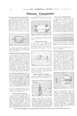
Trough Lubrication for Gearboxes.
The Wolseley Tool and Motor Car Co., Ltd., and A. J. .Rowledge, No. 20,288, dated 13th September, 1911.—The specification describes means for lubricating change-speed gears, differential gears, and other toothed gearing. In the drawing a change-speed gear is shown. Each wheel of an inter-engaging pair runs in a trough of oil which is kept constantly supplied in excess by an oilpump. The oil overflows into a sump in the bottom of the gearcase from which it is drawn by the pump. Suitable o 1 checks and returns are provided adjacent to where the shaft runs through the ends of the gearbox.
Improved Crankshaft Lubrication.
A. de Coninck, No. 12,862/12, dated the 14th July, 1911, under the International Convention.—In four-cylinder engines without a central bearing, it is difficult to lubricate the two central crank pins automatically owing to the action of centrifugal force. According to this invention, oil is supplied under pressure from each end of the crankshaft. A continuous conduit extends from each end bearing, to the centre of one of the central cranks, and from these centres supplementary conduits extend in opposite directions along the cranks. One of the supplementary conduits supplies oil to the outer crank pin, and the other to
one of the central crank pins. The oil thus flows in opposite directions from th, centre of the crank, and its flow is assisted by centrifugal action.
Another Roller Bearing.
L. de M. Ellis, No. 19,446, dated 31st August, 1911.—This invention consists of a roller bearing comprising tapered or plain rollers carried by cage rings which are mounted free on the shaft. The cage rings are connected together by cross studs inserted alternately with the rollers. In the construction shown the bearings are applied to a wheel for a motor vehicle, and are in pairs on conical seats. The bearings may he adjusted by drawing together the inner cones, or by separating the outer cones in the wellknown manner. The cage with its rollers forms a complete unit which is entirely free of the shaft and of the rest of the hearing.
Valve-spring Lifter.
T. R. Eaves, No. 15,402, dated 3rd July, 1911.—A simple device for lifting engine-valve springs comprises two arms hinged together. with a nut and screw fixed between them by which the the opening can be adjusted. The ends of the arms are forked to enable the device to be inserted around the valve etem and the tappet. For convenience in use a handle is provided at the other end of the lower lever.
Improved Shock Absorbers.
L. P. C. j. jacquet.—No. 8614, dated 11th April, 1912.—In the application of shock absorbers to the springs of vans, different patterns have to be used according to whether the spring shackle is in tension or compression. This specification describes adapters which will permit one type of absorber to be used in either case. The adapter consists of a curved link forked at its upper end and formed at its lower end for connection by a bolt to the spring elements of the absorber.
New Tire-making Method.
D. Maggiora, No. 15,417, dated 3rd July, 1911.—This invention relates to the manufacture of solid tires. A core of india-rubber is covered with tubes also of india-rubber. In the construction shown the core is surrounded with three tubes which are in short lengths for ease in placing them in position upon the core. It will be understood that if all the tubes were of the same size to commence with, the outer tube would be at a greater tension than the intermediate tube, which in turn would be at a greater tension than
the inner tube. By adopting this unproved constructional method greater resiliency is obtained.
Novel Engine Detail Construction.
N. A. Christensen, No. 15.473, dated 3rd July, 1911.—This invention relates to the construction of various engine details tending to simplify the construction of internal-combustion engines. As will be seen from the larger figure, the crankshaft directly drives the camshaft through a two-to-one gear. Extending transversely from the camshaft is a cross shaft driven by gearing from the camshaft. This cross shaft drives the magneto and also an air compressor which supplies air for pumping up tires or for other purposes. The cross shaft also drives by means of gearing a fan shaft which runs parallel to the camshaft. Referring to the smaller figure, it will be seen that the gear-wheel on the camshaft has " herring-bone " teeth, the teeth on one side being longer than those on the other side. The specification also describes a construction of camshaft bearing whereby the camshaft with the cams. gears and bearings can be pulled out of the crankcase merely by undoing a few studs, and there is also a very convenient method described of mounting the inlet and exhaust manifolds to permit of ready dismounting. The inventor claims that this method of construction enables the engine to be assembled and dissembled without disturbing the earns or other set parts.