


A New English-built Motor Escape.
Page 11
Page 12
Page 13
If you've noticed an error in this article please click here to report it so we can fix it.
First Published Description of a Model, Embodying Many Novel Features, Shortly to be Delivered to the L.C.C.
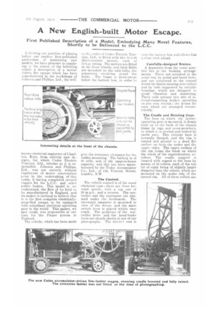
liullowing our practice of placing before our readers first-published particulars of interesting new models, we have pleasure in supplying in the course of the following article a description of a motordriven fire escape which has been manufactured in the workshops of Johnson and Phillips, Ltd., the well known electrical engineers of Chadton, Kent, from entirely new designs, for which Cedes Electric Traction, Ltd., informs us it is responsible. Johnson and Phillips, Ltd., was not entirely without experience of motor construction prior to the undertaking of this order, it having completed several chassis for the L.C.C. and other public bodies. This model is, we understand, the first of it& kind to be manufactured in England, and its maker is inclined to believe that it is the first complete electricallypropelled escape to be equipped with subsidiary electrical operating gear in the world. This maker, we may recall, was responsible at one time for the Pieper system in England. The vehicle, which has been made to the order of Cedes Electric Traction, Ltd., is fitted with two SO-volt direct-current motors, each of 15 h.p. rating. The motors are fitted in the front wheels, and their fields are mounted on the axle-hubs, the armatures revolving round the fields. The frame is down-swept below the battery box, in order to give the necessary clearance for the ladder mounting. The battery is of SO cells, and of 195 ampere-hours capacity, and this has been manufactured by the Tudor Accumulator Co., Ltd., of 119, Victoria Street, London, S.W.
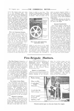
The Control. The vehicle control is of the usual electrical type ; there are three forward speeds, with a top one of 20 m.p.h., and a reverse. The controller and the resistance are situated under the footboards. The necessary ammeter is mounted in view of the driver, and the main switch lever is placed within easy reach. The positions of the controller lever and the hand-brake lever are clearly shown in one of our photographs. The driver's seat is over the battery box and allows him a clear view ahead.
Carefully-designed Brakes. A departure from the usual practice lies in the braking arrangements. These are actuated in the usual way by pedal and hand lever, and are connected to the control levers by chains running over rollers and by rods supported by suitable bearings, which are designed to avoid vibration and chattering. These rods actuate two sets of internal-expanding brakes operating on -the rear wheels ; the drums for each wheel are arranged concentrically.
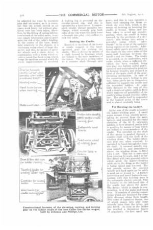
The Cradle and Hoisting Gear. The base on which the ladderoperating gear is mounted, is firmly built on to the back of the chassis frame by tugs and cross-members, to which it is riveted and locked by castle nuts. This circular base is inwardly flanged, and the rim is turned and ground to a dead flat surface on both the under and the upper sides. The upper surface of the rim forms the track on which the whole of the superstructure revolves. The cradle support is located with regard to the base by means of 16 rollers, each of the top lot of eight being of slightly larger diameter than the others, which are mounted on the under side of the turned rim. All of these rollers can
be adjusted for wear by eccentric pins and set-screws, as it is essential that the rollers should at all times work freely yet without play. Great care has been taken, therefore, by the fitting of spring lubricators to each of the roller axles, to en sure ample lubrication and to minimize the risk of the table's binding. In the centre of the base, firmly held relatively to the chassis, is a stationary worm wheel of large diameter, and this, by means of sproe ket wheels and a chain drive, in combination with a worm which rie volves round the fixed worm wheel, forms the medium around which the xhole superstructure is revolved.
A locking lug is provided on the circular-turned rim, and this is operated by a hand lever. A coarsepitch double thread operates two clamps, which securely grip both sides of the rim when the hand lever is brought into play ; this suffices to lock the table.
Rocking the Cradle.
Mounted in the front of the tower or cradle support is the handoperated gear for rocking the cradle. This is driven by means of a shaft housed in bearings which are bolted to the main members of the tower. The drive is then taken to a counter shaft through spur
gears, and this in turn operates a third shaft carrying the drum on which the wire belt, which is the means of hoisting or lowering the cradle, is wound. Great care has been taken to avoid any possibIt mishap, when the cradle is being lowered, by the provision of a dis., clutch ; this brings into action a powerful sprag which "takes charge" in the event of the operator losing control of the handle. Additional safety pawls are provided on the shafts on the outer sides of the main-shaft bearings between the handles and the frame. The cradle is provided, on its undersides, with racks, which, when a sufficient elevation has been reached, bring into play two further safety pawls, operated and maintained in position by balance weights; and situated in front of the main shaft of the gearelevating mCchanism. in case of the operating gear's failing in any way, these pawls are in themselves sufficient to support the cradle and the extended ladders. At some little distance to the rear of this rack a dead-end safety catch is fixed which removes all possibility of the cradle's being wound over the safety line. The cradle itself is suspended at the highest point of the tower and is almost. centrally hung.
For Hoisting the Ladder.
At the rear of the cradle is located the ladder-winding gear. A small series wound. 6 h.p. electric motor, taking its current from the main battery, and intended for the rapid elevation of the 80 ft. extension ladders, is here situated, and is held in position by means of lugs which are bolted to cross-members of the cradle. The sprocket on the shaft of this motor is meshed through a counter shaft with the shs ft of the winding drum. The ladder-extension gear can, when required, be operated by hand through the counter shaft. A screwed spindle running parallel to, and immediately above, the winding drum; is fitted with a nut. This nut is prevented from rotating by a pin, and it is further fitted with two grooved rollers which guide the ladder-elevating cable on to the drum as the ladder is being raised and lowered. The nut travels across the screwed snindle and back again as the cable is paid out or wound in A further interesting and novel feature in connection with this hoisting gear is the automatic electric cut-out. This is located on the left-hand side of the cradle ;list above the motor. The device, which is simple in construction, is of the make-and-break tyne. it consists of circular copper strips which are insulated for some little distance along their length. Two arms of ingenious design, one of which comes into play some seconds later than the other, are also fitted. As soon as the ladder has reached a dangerous degree of angularity, the first small: arm leaves the copper strip and slides on to the insulated part. The second arm then snaps quickly into play, and the motor is immediately cut out. This device, it is confidently expected by those responsible for the design, will remove any possible danger of the ladder overshooting the safety limit of extension. The control for the motor is situated at the extreme rear of the cradle, and safety pawls are fitted on each side of the countershaft. A hand-operated shoe brake is fitted, so that. a check may be placed on the ladder during lowering.
New and Improved Details.
The chassis is so designed that almost every operation can be carried on simultaneously. The handles which are used throughout for hand-operations on this model, are collapsible and can be folded up when not in use. This is plainly shown in the photographs reproduced on the previous page. An accessory marking, in itself, a notable improvement, is the type of quick-action jack which is employed when the vehicle is stationary and the ladder is in use. It has been the general practice, in motor fireescape design, to carry jacks slung in position on the underside of th.. frame in order to save time. This practice is objectionable on account of the small road clearance which it entails. The new jacks, one of which is well shown in the small photograph shown on this page, will be carried in boxes 9cured to the footboard and the chassis. They are provided with spherical balljointed bases, and the heads, which are of T-section, are intended to slide in special channel bolted to the under-side of the frame members, and to register the right position without time being wasted in experiment, or the risk of accident being taken. Polack tires, 880 mm. by 120 mm, twins on the back and singles on the front, are fitted.
General Conclusions.
This model marks a distinct advance in the design of the motor fire-ladder, and, in our opinion many of the features incorporated here, will eventually be adopted as standard practice by other makers. The chassis contains many novel departures, of which the arrangement of the details is by no means the least. We may remark that all parts are interchangeable, and that no trouble has been spared to ensure the many minor details in the chassis being work-perfect. Johnson and Phillips is to be congratulated on carrying out its contract satisfactorily, and the L.C.C. Fire Brigade is also to be congratulated on having the foresight to order this new motor fire appliance. We are given to understand that further similar orders are imminent, should this new model be as satisfactory in service as early tests would indicate.