Know Your Air Brakes
Page 44

If you've noticed an error in this article please click here to report it so we can fix it.
Part 5—The Separate Unloader Valve
have discussed the compressor mounted unloader valve and indicated how it is arranged that a steady pressure can be maintained in the reservoir without overload. Another method of governing and unloading is where the valve is either tank or chassis mounted, but again in the line between compressor and tank.
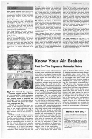
Although the operating features are very similar to the compressor-mounted valve, there is one notable difference—that is, surplus air is exhausted to atmosphere. This unloader valve can be described as follows: The body is a single casting, the governor valve and its adjuster screw forming a threaded assembly in the top of the casting. The screwed adapter and the inlet port from the compressor comes in midway at the side, with the delivery port opposite. The exhaust valve assembly and the vent to atmosphere are at the base of the casting.
Air arriving at the inlet port from the compressor passes through the filter just inside the screwed adapter and travels across the body to the non-return valve positioned in the delivery port adapter. Pressure on this valve overcomes the valve spring, the air then passing straight out of the delivery port to the reservoir.
Above this non-return valve is mounted the governor ball valve, which has a top and bottom seating and a small vent to atmosphere at the side. Therefore the chamber of the governor valve is at atmospheric pressure the whole time the ball valve is held on the bottom seating by its compression spring above. A small drilled passage from the head of the centrally positioned unloader valve communicates with the governor valve chamber. Therefore the head of the unloader valve chamber is also at atmospheric pressure with the ball on the bottom seating.
In the operating sequence the governor valve is held on the lower valve seat by its own spring, which means that air pressure from the reservoir is already behind the nonreturn valve and has access to the underside of the ball valve through a small drilled passage connecting the delivery port to the governor ball valve chamber. As the compressor charges the reservoir, and maximum working pressure is reached, the ballvalve spring is overcome, the ball is lifted from the lower seat to the upper one, and the vent to atmosphere is closed. Full pressure is then admitted to the governorvalve chamber and also to the head of the unloader valve via the small drilling.
This pressure at the head of the unloader valve is acting against the exhaust valve spring in the base of the valve and, as the air pressure overcomes the spring pressure, the unloader valve moves down. The exhaust valve, which is actually the other end of the unloader valve spool, moves from its seat and the excess air passes through to atmosphere via a check valve designed to keep dirt from entering the exhaust valve.
The governor valve stays open, with the ball on the upper seat, until the reservoir pressure drops to 90 p.s.i., then as the governor spring regains control the ball moves again to the lower seat, closing off the air pressure and again opening the vent to atmosphere via the open, upper valve seat. At the same time, the air pressure on the head of the unloader valve is exhausted to atmosphere, that valve regains its upper position from the lift of the exhaust valve spring, and the exhaust valve is closed, the air from the compressor once again moving through the non-return valve to the reservoir.


