


A Low-powered Vehicle for Farm Use
Page 26
If you've noticed an error in this article please click here to report it so we can fix it.
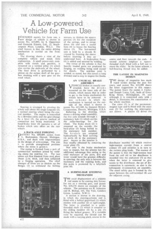
IbiTENDED mainly for farm use, a I new design of vehicle is shown in patent No. 613,092, by S. Opperman and Ganwiek Estates, Ltd, 13, Southampton Place, London, W.C.1. The chief feature is that the entire driving mechanism is carried on the front wheel.
• The drawing shows a view of the complete vehicle and needs little explanation. A small power-unit, complete with clutch and gearbox, is mounted on a vertical pillar (1) which also carries the stub-axle of the wheel. The final drive is performed •by a pinion on the output shaft of the gearbox meshing with a spur gear on the road wheel.
Steering is arranged by pivoting the whole unit abont the single king-pin (2), :s. normal steeling wheel being the control member. The engine is controlled
• by a Bowden cable and the gear-change .by a lever (3), the precise, method of connection not being mentioned. A hand-brake lever (4) operates 'a set of brakes which take effect on the fear • . wheels A BACK-AXLE FORGING
PATENT Ni). 609,489, comes from 'L. Bilekendale, Detroit; -Michigan, U.S.A.,' and deals with improvements in the design of axle-casings. The aim i.to provide strengthened portions' where the stress is greate.A. • The casing is formed from a pair of symmetrical members joined by welding along the mid-line (1).• The two pieces are first blanked from.steel plate
about thick, and then subjected to . a forging operation. The chief changes of form are to thicken up the flanges (2) to withstand the bolting stresses, to thicken the square portion (3) for the reception of the springs, and to swage down the end into a round boss (4) to house the bearing sleeve (5). The last-named unit is held by a shrunk fit created by freezing the sleeve before inserting it into an • undersized bore. A brake-plate flange (6) is added and secured by welding.
The virtue of the scheme is that the heavily loaded parts are produced .by forging, no welding being used except for details. The mid-line joint is welded, as stated, but this covers a long distance and is easy to inspect for faults.
AN UNUSUAL BRAKE ASSEMBLY VEHICLE brakes as usually con . structed, have the dr u nis mounted on the inner side of the wheels, which means that in order to get to the brake mechanism the wheels have to be removed. A new sc heme in which the mechanism is located on the outside of the wheel is shown in patent No. 613,340, by General Motors Corporation, Detroit, Michigan, U.S.A. Referring to the drawing, which shows a driving wheel assembly, the live axle extends through a stationary hub (1) which carries the roller-bearings for the wheel. The brake drum (2) is mounted on the outside, the back-plate (3) being bolted to the stationary hub member. The brak es are actuated hydraulically by fluid arriving via ports (4) in the stationary part. Access to the interior is thus readily obtained by removing the cover plate (5).
Not only is the brake mechanism easy to inspect, but the scheme has the additional advantage that owing to the total enclosure of the parts, dirt and water would have the greatest difficulty in entering; the only way is between the stationary and the running hubs, and this point is protected by a labyrinth joint (6).
A SLIDING-BAR STEERING MECHANISM
T'axial displacement of a slidable rod seems to be coming into favour for use as a steering gear, and Patent No. 610,174 shows an example of the scheme. The patentees are R. Johnston and R. Bishop, 145, The Vale, Golders Green, London, N.W.11.
A section is shown in the drawing, in which the steering-column end is fitted with a helical gearwheel (1) which meshes with another (2) at right-auglas. The latter is attached to a quickthreaded shaft (3) which is coupled to . the sliding member (4) by a pin (5) fitting the helical groove. If a variable ratio be required, the thread Can be made with a varying pitch, coarse in the
centre and finer towards the ends. • A second scheme employs a squarethreaded shaft fitted with a full nut to -move the slider. In the latter scheme, a ball-bearing thread may be added.
THE LATEST IN MAGNETO DESIGN
THE design of magnetos has made rapid strides during •the past few years, and patent No. 613,399 shows the latest suggestions in this respect. The patent bears the names J. Carter, and Joseph Lucas, Ltd., both of Great King Street, Birmingham, 19, and although it is concerned only with a detail, it illustrates the construction of the whole machine.
The rotor (1) is of the permanentmagnet type and is fitted with the usual cam (2) for working the linterruptor, not shown. A pinion (3) drives the
'distributor. member (4) which receives high-tension current from a central contact 15) and switches it in turn to the various plug leads. The essence of the patent is that the high-tension lead from the coil (6) to the distributor is moulded into the end-cover (7) so that when the latter is removed to give access to the distributor, the act of disconnection is automatic, as also is the 'subsequent re-connection on assembly. The usual safety gap is formed by the space between the coil-terminal (8) and the adjacent easing.