


Patents Completed.
Page 18
If you've noticed an error in this article please click here to report it so we can fix it.
complete specifications of the following patents will be sent to any address in the United Kingdom upon receipt of eightpence per copy at Sales Branch, Patent Office, Holborn, W.C.
FOLDING WAGON COVER. — Lloyd, No. 22,242, dated 20th October, 1908.—This invention relates to an improved collapsible top or cover for wagons or carts. The frame of the cover consists of a number of sertical bows connected together by toggle links. The vertical bows are provided with antifriction rollers, which run in rails or channels provided on each side of the wagon. These channels have inwardly. turned edges which prevent the antifriction rollers from springing out. The front bow, or that one nearest the driver's seat, is rigidly attached to the rails so that the whole can be removed from one vehicle and may be attached to another.
TIRES.—Hartridge, No. 4,561, dated 28th February, 1908.—According to this invention, a solid tire is secured to the rim or felloe of a wheel in the following manner. At each side of the tire is arranged a floating metal ring or hoop suitably shaped to engage and hold an enlarged portion of the tire. Between this floating ring and a second or outer floating metal ring is riveted a ring of indiaruhrber and canvas or other suitable flexible material, and this extends down the side of the felloe, and it is secured thereto by an inwardly-flanged metal ring and bolts. It will be seen that these flexible rings are the only mimeo. tion between the tire and the rim of the wheel, so that when under load the tire is pressed to a limited extent towards the centre of the wheel, thus adding to its resiliency.
NON-SKID COVERS.—Challiner.— No. 22,051, dated 19th October, 1908.— This invention relates to non-skid covers and particularly to the means for connecting the cover to the rim of the wheel. The rim is provided with additional grooves, and the cover has a number of hooks which engage the grooves provided in the rim.
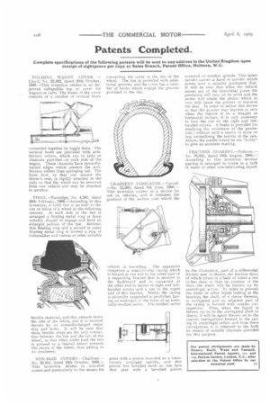
GRADIENT INDICATOR.—Carrad. —No. 12,205, dated 5th June, 1908.— This invention relates to a device for use on vehicles, and it indicates the gradient of the surface over which the vehicle is travelling. The apparatus comprises a semi-circular casing which is hinged at one end to the lower part of a supporting bracket that is secured to the dashboard and is connected at the other end by means of right and lefthanded screws and a nut to the upper end of this bracket. Within the casing is pivotally suspended a pendulum having an extension in the form of an internally-toothed sector. The toothed sector gears with a pinion mounted on a transversely arranged spindle, and this pinion has bevelled teeth on one face that gear with a bevelled pinion mounted on another spinnle. This latter spindle carries a hand or pointer which moves over a suitably graduated dial. It will be seen that when the vehicle moves out of the horizontal pane the pendulum will turn on its pivot and the sector will rotate the pinion which in turn will cause the pointer to traverse the dial. In order to adjust this device so that the pointer may register at zero when the vehicle is on a straight or horizontal surface, it is only necessary to turn the nut on the right and lefthanded screws. A brake is provided for steadying the movement of the pendulum ; without such a means of more or less neutralising the inertia of the pendulum, the needle would be too "lively" to give an accurate reading.
FRICTION GEARING.—Pattison.— No. 16,821, dated 10th August, 1908.— According to this invention friction gearing is arranged to rotate in a bath of water or other non-lubricating liquid.
In the illustration, part of a differential friction gear is shown, the friction discs of which rotate in a bath of water a few inches deep so that on rotation of the discs the water will be thrown up by centrifugal action. in order to prevent the water or other liquid leaking at the bearings the shaft, or a sleeve thereon, is corrugated and an adjacent part of the casing is formed with coarser corrugations. Thus, when the liquid is thrown tip on to the corrugated shaft or sleeve, it will be again thrown on to the coarser corrugations formed in the casing by centrifugal action and from these corrugations it is returned to the bath by means of suitable channels provided for this purpose.