


Carburetter of Novel Design
Page 72
If you've noticed an error in this article please click here to report it so we can fix it.
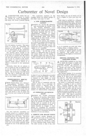
A CARBURETTER which has no fl throttle-valve is ,shown in patent No. 752,702 (E. Clerk,Bourgainville, Old Stony Hill Road. Constant Spring
P.O., St Andrew, Salnaica). The engine speed is varied by controlling the quantity of fuel supplied. A necessity of the functioning of the carburetter is a small supply of high-pressure air.
The drawing shows enough of the construction to illustrate the principle. A jet tube (1) extends into the venturi and has fuel sucked up it in the usual way by the air velocity in the venturi. The supply of fuel is metered by a . tapered needle (shown end-on at 2) which is connected to the accelerator pedal.
Obviously, when the air velocity is low it would not pick up sufficient fuel to run the engine, but in these circumstances an air-jet (3) is brought into action. The air issuing from this blows the fuel like a spray-gun and maintains, it is claimed, a combustible mixture at low engine speeds.
INDEPENDENTLY SPRUNG DRIVING AXLE
FROM Daimler-Benz A.G., StuttgartUnterturkheim, Germany, comes patent No. 752,640, describing a driven axle suitable for use in an independently sprung system. It refers to the type of transmission employing swinging halfaxles and shows a way of using only one universal joint instead of the usual two The two half-axle assemblies are rockably joined by a common rubberbushed pivot (1) supported by a bracket depending from the frame. The pivot is lower than the axle centre-line anda single universal joint (2) is fitted between the two members, the differential and crown-wheel assembly being mounted on one of the half-axle tubes.
The suspension members in the example shown are helical springs (3) but other types may he used.
A NEW SUPERCHARGER ' LAYOUT
PATENT No. 753,197 (W. Glamann and Automobiles M. 'Berliet bolh of 241 Avenue Berthelot, Lyon (Rhone) France) shows a supercharging scheme for the larger sizes of vehicle. The patent mentions that the use of exhaust-driven turbines to power blowers is far from satisfactory because the supercharge drops With falling engine speed; in other words. it iS, not available when wanted most.
In the present scheme, the compressor is driven in tandem with the gearbox through a differential gear so that the reverse of that deicribed occurs; the compressor speed is greatest when the vehicle is at a standstill.
The drawing shows a general layout of the vehicle. At the rear of the. engine is a differential gear (1) having two output shafts, one (2) leading to the gearbox whilst the other (3) .drives a shaft attached to the compressor (4). This is located well to the rear so that its duet (5) can be adequately air-cooled before it reaches the engine. The duet is located at axle height to avoid striking obstacles; this is a point made in the patent.
The air duct is connected with the exhaust system via a cross-pipe (6) which contains a blow-off valve to release surplus air. Numerous other schemes are described, sonic of which employ an eichatist-claven compressor, AN IMPROVED ALUMINIUM ALLOY
PATENT No. 752,802 (Aluminbm ,Company of America, Alcoa Building, Pittsburgh, Pennsylvania, U.S.A.), gives details of an improved light alloy said to be suitable for piston and connecting rods on account • of its good hot-strength and resistance to creep. A typical formula is: Copper 7, manganese 0.7, vanadium 0.1, zirconium 0.15 and magnesium 0.4, all percentages. The remainder is aluminium having the minimum of iron and silicon.
A VEHICLE FOR ROUGH GOING
AN unusual vehicle, designed for 1-1,. agricultural work or for traversing rough or mountainous country, is shown in patent No. 752,953 (L. Caffa, 22 Corso Quintino Sella, Turin, Italy). The chief novelty is that it has only
three wheels, any one of which can be set at a higher or lower level than the rest.
Each wheel is carried on a swinging arm (1) pivoted to the frame Each has a hydraulic jack (2) the setting of which governs the angular position of the arm. They can be temporarily displaced while running, or they can be pre-set
so as to maintain an even keel when running along a sloping surface.
All wheels are powered and all can be steered, or locked against steering as required. The patent gives no particulars of the engine or transmission arrangements.
DRIVING COUPLING FOR INJECTION PUMPS , •
ACOUPLING, suitable for any duty in which the torque is rapidly and continually reversed, is described in patent No. 752,575. The patentees are C. Thorpe and A.E.C., Ltd., Southall, Middlesex, who state that the drive to an injection pump is a particularly suitable application.
The driving member (1) is provided with two dog teeth (2) which are a good sliding fit in slots in an intermediate free ring (3). The driven member likewise has two teeth, also closely fitting two other slots in the ring, 90° away.
So much is a well-known method of making a coupling to give a positive drive. Usually, however, when slack appears between teeth and slots, such a joint tends to rattle, and the present scheme, is aimed at preventing this. Radial movement is resisted by a rubber ring (S) trapped between the two halves of the joint. The ringis assembled under sonic compression and serves to prevent clatter arising when the parts wear.