


:ear Engine in New Double-decker
Page 53
Page 54
Page 55
If you've noticed an error in this article please click here to report it so we can fix it.
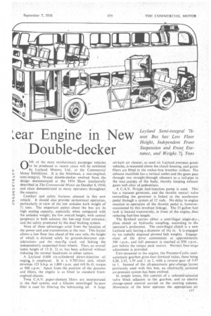
Leyland Semi-integral 78seat Bus hasLow Floor Height, Independent Front Suspension and Front Entrance, and Weighs 71 Tons ONE at the most revolutionary passenger vehicles to be produced in recent years will be exhibited by. Leyland Motors, Ltd., at the Commercial Motor Exhibition. It is the Atlantean, a rear-engined, semi-integral, 78-seat double-decker evolved from the design demonstrated at .the 1.954 Show (exclusively described in The Commercial Motor on October 8, 1954, and, since demonstrated to many. operators throtighqut ,
the country. • ... . • .
Comfort and safety features abound in this new vehicle. It should also provide economical operation, particularly in-view of the low unladen kerb weight of 7+ tons. The important points about the bus are its high seating capacity, especially, when compared with. the nnladen 'weight; the lowoverall height, with central gangways in borh saloons.; the low-step front entrance; and the safety promoted by the dual braking.sYstem. '
Most of these advantages arise from the location of the power unit and transmission at the rear. This layout allows a. low floor line ahead of the rear axle, the height of which is dictated solely by ground-clearance considerations and the steering track rod linking the independently suspended front wheels. Thus, art overall laden height of 13 ft. 2-1 in. has been achieved without. reducing the normal headroom in either saloon. .
A Leyland 0.600 six-cylindered direct-injection oil engin*. is -employed_ It is a 9.785-litre unit, which. develops 125 bhp. at 1,800 r.p.m. and.410 lb.-ft. torque at 900 r.p.m." Apart from the position of the dynamo and filters, the engine is as fitted to standard front
engined chassis.. • Twin C.A.V. paper-element filters are incorporated in the fuel systdm. and a Glacier centrifugal by-pass filter is used for filtering the lubricating oil. A large
oil-bath air cleaner, as used' on Leyland overseas goods vehicles, is mounted above the clutch housing, and gauze filters are fitted to the rocker-box breather orifices. Thd exhaust manifold has a vertical outlet and the gases pass through two straight71hrough silencers to a tail-pipe the rear canopy of the body, thereby keeping exhaust gases-well clear of pedestrians.
„ A C.A.V. N-tYpe fuel-injection.pump is used. This has a vacuum governor, and the throttle venturi valve controlling the governor is linked 'to the accelerator
. pedal through a system_ of 12 rods. No delay in engine reaction to operation of the -throttle pedal is-, however, occasioned by this involved linkage. The 35-gallon fuel tank is located transverSely, in front of. the engine, thus
reducing fuel-line length.. • • • • . • The flywheel carries either. a centrifugal single-dryplate clutch or hydraulic coupling, according to the• operator's preference. The centrifugal clutch is a new Leyland .unit•having a diameter of 161 in, It is engaged by six radially. disposed pivoted bob weights. Engagement of the drive, commences at approximately 500 r.p.m., and full pressure is reached at 850 r.p.m., just before the torque peak occurs.Normal four-stage adjustment is provided.
Unit-mounted to the engine, the Pneurno-Cyclie semiautomatic gearbox gives four forv-rard ratios, these being 4.28, 2.43, 1.59 and..1 to 1, with a reverse gear of 5.97 to I. Instead .of the all-pneumatic gear-change.layout previously used with this box, an electrically actuated
air-pressure system has been evolved. . .
In simple terms, this consists of a solenoid-actuated valve block adjacent to the gearbox, and an electric change-speed control carried on the steering column. Movement of the lever operates the appropriate. air valve, which admits air to the corresponding brake-band power cylinder, as with the normal box: The advantage of this system is that lengthy air pipes between the gearbox and the control lever are eliminated.
' The gearbox has its own lubrication system, and a Purolator filter has been put in circuit with the oil pump. . A bleed from this filter supplies Oil to the gear train at the front of the box which drives the radiator fan..
A fully automatic version of the Pneurno-Cyclic gearbox is to be offered with the Atlanteart. Full details are not yet available, but the gear lever is retained and the box will change gear automatically, depending upon speed and torque, up to the highest gear selected.
The rear of the gearbox carries the angle-drive gearing. This consists of a pair of spiral-bevel gears 'which give a reduction ratio of 1.065 to 1 and take the drive through an angle of 72.
Four-point mounting is used for the engine and gearbox unit. There are two Metalastik sandwich-type rubbers in compression and shear at the front. These mountings are staggered, because the one on the righthand side of the block lies behind the dynamo. Two Metacones support the rear of the unit, these being at a slight angle to provide lateral location and reduce engine oscillations.
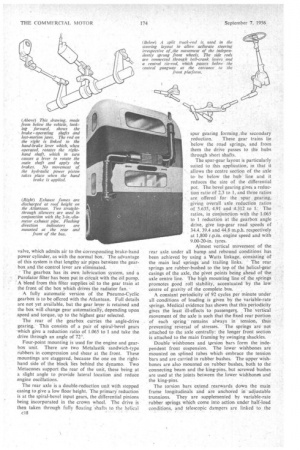
The rear axle is a double-reduction unit with stepped casing to give a low floor height. The primary reduction is at the spiral-bevel input gears, the differential pinions being incorporated in the crown wheel. The drive is then taken through fully floating shafts to the helical c18 spur gearing forming, the secondary _reduction. These gear trains lie below the road springs, and from them the drive passes to die hubs through short shafts.
The spur-gear layout is particularly suited to this application, in that it allows the centre section of the axle to be below the hub line and it reduces the size of the differential pot. The bevel gearing gives a reduction ratio of 2.3 to 1, and three ratios are offered for the .spur gearing, giving overall axle reduction ratios of 5.635, 4.91 and 4.312 to 1: The ratios, in conjunction with the 1.065 to 1 reduction at the gearbox angle drive, give top-gear road speeds of 34.4, 39.4 and 44.8 m.p.h. respectively at 1,800 r.p.m. engine speed and with 9_00-20-in. tyres.
Almost vertical movement of the rear axle under all bump and rebound condition S has been achieved by using a Watts linkage, consisting of the main leaf springs and trailing links. The rear springs are rubber-bushed to the top of the helical-gear casings of the axle, the pivot points being ahead of the axle centre line. The high mounting line of the springs promotes good roll stability, accentuated by the low centre of gravity of the complete bus.
A constant periodicity of 92 cycles per minute under all conditions of loading is given by the variabIe-rate springs. Medical evidence has shown that this periodicity gives the least ill-effects to passengers. The vertical movement of the axle is such that the fixed rear portion of each spring remains always in tension, thus preventing reversal of stresses. The springs are not attached to the axle centrally: the longer front section is attached to the main framing by swinging shackles.
Double wishbones and torsion bars form the independent front suspension. The lower .wishbones are mounted on splined tubes which embrace the tension bars and are carried in rubber bushes. The upper wishbones are also mounted on rubber bushes, both to the connecting beam and the king-pins, but screwed bushes are used at the joints between the lower wishbones and the king-pins.
The torsion bars extend rearwards down the main frame longitudinals and are anchored in adjustable trunnions. They are supplemented by variable-rate rubber springs which come into action under half-load conditions, and telescopic dampers are linked to the lower wishbones. The periodicity of the front suspension is 120 cycles per minute under half load and 103 cycles per minute under full load.
Worm-and-nut steering gives 5.7 turns of the steering wheel from lock to lock, the turning circle being 54 ft. and the swept circle 62 ft. The steering drag link is connected to the wheels through a divided track rod and bell-crank levers. A two-spoke 20-in.-diameter steering wheel is fitted.
Braking safety has been assured by the use of a dual air-hydraulic system. The air-pressure section of the system consists of Bendix-Westinghouse units. A DI pedal valve, working with a single air reservoir, supplies air to twin independent air-hydraulic actuators mounted below the driving platform,..
The The actuators operate hydraulif master cylinders, one of which is piped to the front-wheel units and the other to the rear brakes. Separate reservoirs supply each cylinder. Thus, should one fluid pipe fail in service, the complete braking system does not become inoperative. External cylinders are used. at each-wheel, with open-type brake assemblies.
Mounted on the stub axles, the front brake cylinders actuate 151-in.-diameter assemblies, which have a facing width of 5 in. The rear-brake cylinders are carried on substantial brackets ahead of the rear axle, and are linked to the rear brakes through a system of lost-motion levers and cross-shafts. This mechanism allows completely independent operation of hand and foot brakes whilst utilizing the same final linkages. The rear brakes are of 164-in. diameter, with 6-in.-wide facings.
• The driving position is on a raised floor 111 in. above the entrance platform. This gives excellent driving vision and a clear view of the platform area. This latter feature is important; it means that the driver can have complete control of the operation of the power doors, and leaves the conductor free to collect fares—no small task with 78 seated passengers aboard.
Only two pedals are required—an organ-type accelerator and a wide treadle brake pedal. The.travet of the brake pedal has purposely been made long (21 in.) and with progressive resistance it gives true braking "feel" A pedal pressure of 160 lb. is required for maximum braking.
The instrument panel, which is carried on the steering column, contains a combined speedometer and mileage recorder and oil-pressure and water-temperature warning lights'. The speedometer dial is marked in three colours at the lower speeds to indicate the normal gear changing speeds, the driver being unable to hear the engine note. The instrument panel -carries the gearchange lever on an arm atthe left side.
A conventional pull-on hand-brake lever is located to the right of the driver's seat, and a footrest is provided at the left of the steering column to give the driver somewhere comfortable to put his redundant left foot. The electrical switch board is in the left-hand front corner of the cab and folding arm-rests are provided with the fully adjustable, hide-trimmed seat.
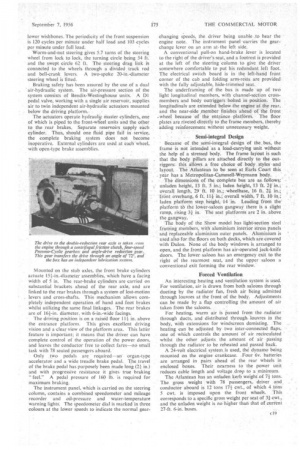
The underframing of the bus is made up of two light longitudinal members, with channel-section crossmembers and body outriggers bolted in position. The longitudinals are extended below the engine at the rear, and the near-side member finishes 'ahead of the front ..wheel because of the entrance platfOrm. The floor plates are riveted directly to the frame members, thereby adding reinforcement without unnecessary weight.
Semi-integral Design
Because of the semi-integral design of the bus, the frame is not intended as a load-carrying unit without the help of a stressed body. The frame layout is such that the body pillars are attached directly to the outriggers: this allows a free choice of body styfes and layout. The Atlantean to be seen at Earls Court this year has a Metropolitan-Cammell-Weymarm body.
The dimensions of the complete bus are as follows; unladen height, 13 ft. 5 in.; laden height, 13 ft. 21 in.; overall length, 29 ft. 10 in.; wheelbase, 16 ft. 24 in.; "front overhang, 6 ft. 114in overall width, 7 ft 10 in laden platform step height, 14 in. Leading from the platform -0) the lower-saloon gangway there is a slight
rarnp, rising in. The seat platforms are 2 in. above the gangway.
The body of the Show model has light-section steel framing members, with aluminium interior stress panels and replaceable aluminium outer panels. Aluminium is used also for the floors on both decks, which are covered with Dulon. None of the body windows is arranged to open, and the front platform has air-operated jack-knife doors. The lower, saloon has an emergency exit to the right of the rearmost seat, and the upper saloon a conventional exit forming the rear window.
Forced Ventilation An interesting heating and ventilation system is used. For ventilation, air is drawn from both saloons through. ducting by the radiator fan, fresh air being admitted through louvres at the front of the body. Adjustments can be made by a flap controlling the amount of air taken from the saloons.
For heating, warm air is Passed from the radiator through ducts, and distributed through louvres in the body, with extensions for windscreen demisting. The heating can be adjusted by two inter-connected flaps, one of which controls the amount of air recirculated whilst the other adjusts the amount of air passing through the radiator to be reheated and passed back.
A 24-volt electrical system.is used, the dynamo being mounted on the engine crankcase. Four 6v. batteries are arranged in pairs ahead of the rear wheels in enclosed boxes. Their nearness to the power unit reduces cable length and voltage drop to a minimum.
The Atlantean has an unladen kerb weight of 74 tons. The gross weight with 78 passengers, driver and conductor aboard is 12 tons 171 cwt., of which 4 tons 5 cwt. is imposed upon the front wheels. This corresponds to a specific gross weight per seat of 3+ cwt., and the unladen weight is no higher than that of current 27-ft, 6-in. buses.