


30-ft. Double-decker • from Daimler
Page 50
Page 51
If you've noticed an error in this article please click here to report it so we can fix it.
ANEW 30-ft.-long double-decker chassis has been introduced by Transport Vehicles (Daimler), Ltd., Coventry. It is offered with either the Daimler 10.6-litre engine, in which case the chassis is known, as the C.V.D. 650/30, or with the Gardner 6LW engine (C.V.G. 6/30).
The C.V.G.6/30 to be exhibited at the Commercial Motor Show will have a Willowbrook 75-seat body weighing under 3 tons. It is of lightweight steel construction, all panels and some parts of the framework being popri4eted. The Show 411 vehicle is for Walsall • Corporation. The Daimler 10.6
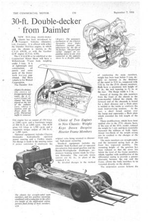
(Right)To obviate _ the entry of foreign matterand water, the A. C. centrifuge air cleaner has been placed on the left of the radiator core, where it receives cool air direct from the grille. Thenormal baffle is removed.
litre engine has an output of 150 b.h.p. at 2,000 r.p.m. and a maximum torque of 460 lb.-ft. at 1,000 r.p.m. The 6LW gives 112 b.h.p. at 1,700 r.p.m. and a maximum torque output of 358 lb.-ft.
at 1,300 r.p.m. • Optional equipment includes Clayton Dewandre hydraulically operated power steering and a Twiflex clutch. No change is made in the steering ratios if power assistance employed, the original ratio being retained to discour • age high-speed cornering.
Standard equipment includes the Daimler fluid flywheel and air-operated pre-selective four-speed gearbox and the .--fiendix-Westinghouse diaphragm airpressure braking system made by Clayton Dewandre. The rear-axle worm centres are 81 in., in place of the standard 8 in.
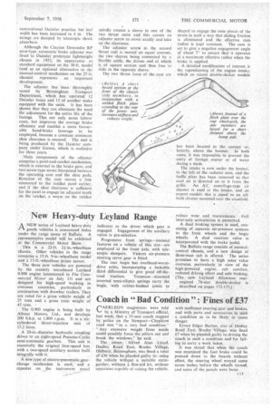
By detailed changes in the method of reinforcing the, main members, weight has been kept below 5 tons, despite an increase in the thickness of the metal to 9/32 in., compared with 7/32 in. for.the 27-ft chassis members. Both have a Maximum web height of 11 in., the web tapering to 51 in. at • the rear. The flange width is 3 in.
Instead, of boxing the side members from the front of. the chassis fo the cross-member behind the clutch, the forward end of the channels is boxed for a short distance and a flitch plate is welded to the inside to reinforce the.
main load-carrying sections. At the rear, a short boxed section over the bump pad supersedes a flitch plate which extended the full length of the arch.
These modifications, which have beon applied also to the 27-ft. chassis, have, in the case of the 30-ft. model, reduced the weight by 1 cwt. and have materially increased the stiffness of both• types. About two-thirds of the weight saving can be credited to the changes at the front end.
The main members arc straight-sided, and the increased spring base at the front has improved stability. The mounting height of the gearbox has been reduced so that the cover lies below the level of the frame members, which, together with modification of the differential casing to provide a greater clearanec between the top and the frame, allows the body members to be mounted directly on the chassis.
The suspension system follows the conventional Daimler practice, but leaf width has been increased to 4 in. The strings are damped by telescopic shock absorbers.
. Although the Clayton Dcwandre RP strut-type automatic brake adjuster was fitted to Daimler prototype lightweight chassis in 1952, its appearance as standard equipment on the 30-ft. model (and as an optional alternative to the manual-control mechanism on the 27-11. chassis) represents an important development.
The adjuster has been thoroughly tested by Birmingham Transport Department, which has operated 12 Daimler buses and 12 of another make equipped with the units. It has been shown that they can eliminate the need fbr adjustment for the entire life of the facings. This not only saves labour costs, but improves the average brake efficiency and enables a more favourable hand-brake leverage to be employed, because a constant minimum shoe clearance is ensured. The unit is being produced by the Daimler company under licence, which is exclusive for three years.
Main components of the adjuster comprise a pawl-and-ratchet mechanism, which is external to the brake gear, and two screw-type struts interposed between the operating cam and the shoe pads. Rotation of the cam moves a link connected to the ratchet pawl carrier, and if the shoe clearance is sufficient for the pawl to engage an adjacent tooth on the ratchet, a worm on the ratchet spindle rotates a sleeve in one of the two thrust units and this causes an adjuster screw to move axially and take up the clearance.
The adjuster screw in the second thrust unit is moved an equal amount, the two sleeves being connected by a flexible cable, the driven end of which is of square section and thus free to slide in the opposite sleeve.
The two thrust faces of the cam are
shaped to engage the nose pieces of the struts in such a way that sliding friction is eliminated and the effective cam radius is kept constant. The cam is set to give a negative engagement angle of about 7° to ensure that it operates at a maximum effective radius when the brake is applied.
A detailed modification of interest is the repositioning of the engine intake, Which on recent double-decker models has been located in the canopy or, latterly, above the bonnet. In both cases, it was impossible to prevent the entry of foreign matter or of water during a wash.
The intake is now under the bonnet, to the left of the radiator core, and the baffle plate has been removed so that cool air is directed on. to it from the grille. An A.C. centrifuge-type air cleaner is used at the intake, and on export models this is piped to an oilbath cleaner mounted near the manifold.