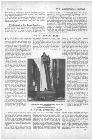
THE HYDRAULIC HOIST.
Page 15

If you've noticed an error in this article please click here to report it so we can fix it.
TIPPING BODIES, which were at one time almost cqmpletely Confined to municipal vehicles, are becoming more and mare popular amongst general users of commercial vehicles, and with their popularity the question of providing suitable tipping gears is becoming ane of considerable moment. In an. article entitled " Types of Tipping Gears" which was published by us in Decerriber last, we described practically all the successful gears, and amongst them Was the hydraulic hoist, for which the Hydraulic Hoist Co., 91, Lord Street, Southport, are the sole concessionnaires for this country.
This hoist has been very favourably received by both our manufacturers and users, and it is employed extensively by such . well-known ooncerns as Leyland Motors, Ltd., and Calcdon Motors, Ltd.
Owing to its position between the cab and the body, it does not haveto bear the same strains as does -the hydraulic rani` situated close in front of the back axle, tand, as ample ream can be left between the cab and the body. liii difitensions are not restricted by such considerations as-ground clearance and limited space' between the body and the .chassis ; also, the oil pressure does not have to be nearly so high as . in those rams which' exert their power at about the Middle of the body. Therefore, there is legs difficulty as regards oil leakage. With this hoist, the barrel does not have to swivel at its. base, and for this reason also there is less 'liability of leakage.
The hoist Consists of a, cylinder 6 ft, high, upon which are fixed the pulleys taking the roll and weight and the lifting cables. A cross arm is fixed at the base to take the strain, and the cables
are fastened permanently Go this. The other ends of the cable are attached to two specially:bent body brackets, which are bolted perpendicularly to the rear of the tipping body and project some distance below it. The oil pressure is derived • from aplunp attached independently underneath, the cross members
bearing the cylinder. This pump is driven by a roller chain from a sprocket provided with a dog clutch and attached to the clutch Shaft of the chassis. In certain -chassis modifications have to be carried out to enable this to be done, 6..a the sprocket must naturally be situated on a shaft which continues to revolve when the Chassis is at rest with the engine working., Two. 'special levers. control the working of the hoist.' One situated at the left side engages the sprocket clutch and starts
the 13-amp working; the lever at the right
opens the delivery and supply valves to the pump. This causes the oil to be forced into the cylinder below the hoist piston,' thereby raising the latter., Further move. ment of this lever closes both valves so that the hoist remains extended so long as desired. The pump sprocket clutch is, of course, disengaged when the highest required point il reached and after the valve has been
closed. Another movement of the lever orb the right opens the pump valves and allows the oil to flow from below tho piston to the reservoir, and the hoist piston Consequently descends, the speed of this descent being easily regulated.
This hoist is snitalale for corn
. niercial vehicles carrying from three to seven tons,--and is guaranteed to lift the latter weight. Its popularity and efficient Working are shown by the fact that 90 per cent, of the commercial vehicle manufacturers in Areerica fit this device as standard on their tipping wagons.
For simplicity of construction and fitting combined with ease of operation ancl accessibility for any little adjustments wbich may have to be made, this hoist is one of the best and most-reliable on the market.


