Internal combustion engine 3
Page 67

If you've noticed an error in this article please click here to report it so we can fix it.
ONTRARY to what a beginner ight at first suppose, the inlet d exhaust valves of the ternal combustion engine do t open and close exactly at DC and BDC.
In fact, the inlet valve opens efore TDC and closes after BDC allow as long a period as ossible for the intake of the ew charge. By allowing the let valve to remain open until te in the cycle, advantage is ken of the momentum of the oming gas to fill the cylinder completely as possible.
As the exhaust valve is still pen at this time the rapidly oving outgoing gases help to aw in the income charge.
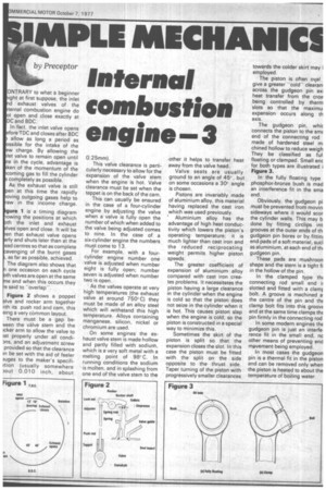
gure 1 is a timing diagram owing the positions at which th the inlet and exhaust Ives open and close. It will be en that exhaust valve opens rly and shuts later than at the ead centres so that as complete avenging of the burnt gases as far as possible, achieved. The diagram also shows that one occasion on each cycle th valves are.open at the same e and when this occurs they e said to "overlap".
Figure 2 shows a poppet lye and rocker arm together rith its push rod and cam, this eing a very cOmmon layout. There must be a gap beveen the valve stem and the )cker arm to allow the valve to at properly under all condi3ns, and an adjustment screw provided so that the clearance In be set with the aid of feeler iuges to the maker's specifiition (usually somewhere out 0.010 inch, about This valve clearance is particularly necessary to allow for the expansion of the valve stem when the engine is hot. Valve clearance must be set when the tappet is on the back of the cam.
This can usually be ensured in the case of a four-cylinder engine by adjusting the valve when a valve is fully open the number of which when added to the valve being adjusted comes to nine. In the case of a six-cylinder engine the numbers must come to 13.
For example, with a fourcylinder engine number one valve is adjusted when number eight is fully open; number seven is adjusted when number two is open.
As the valves operate at very high temperatures (the exhaust valve at around 750=C) they must be made of an alloy steel which will withstand this high temperature. Alloys containing manganese, silicon, nickel or chromium are used.
On some engines the exhaust valve stem is made hollow and partly filled with sodium, which is a very soft metal with a melting point of 98° C. In running conditions the sodium is molten, and in splashing from one end of valve stem to the -Other it helps to transfer heat away from the valve head.
Valve seats are usually ground to an angle of 45c'. , but on some occasions a 30° angle is chosen.
Pistons are invariably made of aluminium alloy, this material having replaced the cast iron which was used previously.
* Aluminium alloy has the advantage of high heat conductivity which lowers the piston's operating temperature; it is much lighter than cast iron and the reduced reciprocating weight permits higher piston speeds.
The greater coefficient of expansion of aluminium alloy compared with cast iron creates problems. It necessitates the piston having a large clearance in the cylinder when the engine is cold so that the piston does not seize in the cylinder when it is hot. This causes piston slap when the engine is cold, so the piston is constructed in a special way to minimize this.
Sometimes the skirt of the piston is split so that the expansion closes the slot. In this case the piston must be fitted with the split on the side opposite to the thrust side. Taper turning of the piston with progressively smaller clearances towards the colder skirt may I employed. .
The piston is often ov,a1 give a greater "coldclearani across the gudgeon pin axi heat transfer from the crov being controlled by therm slots so that the maximu expansion occurs along th axis.
The gudgeon pin, whic connects the piston to the SME end of the connecting rod made of hardened steel rn. chined hollow to reduce weigh They be classified as ful floating or clamped. Small enc for both types are illustrated i Figure 3.
In the fully floating type phosphor-bronze bush is mad an interference fit in the srna end.
Obviously, the gudgeon pi must be prevented from movin sideways where it would scor the cylinder walls. This may b done by fitting circlips int grooves at the outer ends of th gudgeon pin bores or by fittinj end-pads of a soft material, sucl as aluminium, at each end of till gudgeon pin.
These pads are mushroon shape and the stem is a tight fi in the hollow of the pin.
In the clamped type th connecting rod small end slotted and fitted with a clamr bolt. A groove is machined a the centre of the pin and th( clamp bolt fits into this groovE and at the same time clamps thc pin firmly in the connecting rod In some modern engines the gudgeon pin is just an interf& rence fit in the small end, nc other means of preventing end mpvement being employed.
In most cases the gudgeon pin is a thermal fit in the piston and can be removed only when the piston is heated to about the temperature of boiling water.


