


Liquid-cooled Brakes
Page 90
If you've noticed an error in this article please click here to report it so we can fix it.
,4 BRAKE-COOLING system is the subject of patent No. 840,734. Its novelty is the means used to promote intimate contact between the coolant and, the heat source. (P. Damiron, 56 Avenue Roche, Paris 8.) The drawing shows a section of one form of drum and shoe. The friction facing, shown at 1, is attached to the, drum and rotates with it. The shoe is a hollow member filled with coolant (2).
The contact surface (3) of the shoe is made of very thin metal; about 0.40 in. As this face would not, on its own, withstand the thrust of braking, hydraulic pressure developed by the coolant supports it in operation.
The cooling liquid is carried in a complete Circuit of piping incorporating a pressure pump and radiator. The hydraulic pressure on the thin face is said to make the braking force uniform over the whole area and so prevents local wear of the friction material.
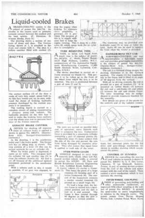
EXHAUST BRAKE CONTROL
I-1 A DEVICE for shutting off injection when an exhaust brake is applied is shown in patent No. 840,913. (Daimler Benz A.G., Stuttgart-Untertiirkhei in. Germany.) .
In the drawing, 1 is the accelerator pedal and 2 the brake pedal. The former unit has an idling stop, as shown. The stop consists of a lever (3) that can be moved upwards by an air cylinder (4).
When the brake pedal is depressed, it opens an air valve. This energizes both the cylinder (4) and another one -(5) to close the exhaust throttle (6). Al] fuel is cut off because of the additional upward movement permitted to the accelerator pedal.
With a scheme such as this, it would be possible, if no gear was engaged, to
stop the engine when braking. To eliminate this possibility, a. governor, (7) is provided. The purpose of this is to supply suffi cient Mel to keep-the , engine running.This is, done by a slide
valve (8) which opens both-the:air ders to atmosphere.'
TYRE' REMOVINGTOOL A_ TOOL to break lyre -heath. from.: • 1.71wheel rims is the sehjee.t of Patent No. 842,876. (C. Morle, Napier House, 24-27 High Holb-orn, London, W.C.1, communicant of The Automotive Equipment Manufacturing Company, 11,000 South Alameda Street, Lynwood, California, U.S.A.) The device described is carried on a frame mounted on wheels (I). This permits it to be rolled up to the front of the wheel from which the tyre is to be removed. The tyre is positioned between a pair of jaws (2 and 3).
The jaws are carr.ed on parallel links and, in operation, move towards each other to compress the tyre. Compressive force is provided by a pneumatic cylinder containing a pair of opposed pistons (4).
Adjustable stops (5) make contact with the side of the rim arid prevent the tyre from being damaged by excessive pressure. They also ensure that equal force is applied to each side of the cover.
OVER-WIDTH LOADS A VEHICLE designed to carry large 1—L concrete slabs which, when laid flat, exceed normal vehicle width, is covered by patent No. 839,997. (D. Dale and British Reinforced Concrete Engineering Co., Ltd., Lichfield Road, Stafford.) A tractor vehicle (1) carries a framework (2). This bears the pivot of a large trunnion (3) forming part of a lattice framework (4). The rear end of the framework contains a similar coaxial trunnion (5) pivoted on a small bogie (6).
To load a large slab, the lattice frame is rotated into a horizontal position and the slab is laid on it and secured. The frame is then rotated through 90 degrees so that the slab is turned to a vertical position. , The trunnions may be provided with hydraulic rims (7) to raise or lower the load. lacks (8) can be used to support the front when the tractor is detached.
DAIMLER BENZ TILT CAB :A FORWARD-CONTROL cab that accommodates te full widthbench seat and proVides good engine accessibility is the subject of patent No. 841,233. (Daimler-Benz A.G., Stuttgart-Unterterkhcim. Germany.)
The cab is a forward tilting design; the drawing illustrates it in the forward position. The engine (1) lies longitudinally in the frame and is tilted at an angle of 60 degrees from the vertical.
With all its driving controls, the cab is pivoted on a pair of brackets (2). It is mounted on rubber blocks (3) between the cab and a sub-frame (4) and others (5) between the cab and chassis frame. The latter mountings may be wedge " shaped to provide transverse location for the assembly.
Few details are given of the pivots for the controls and of the -radiator connee
tions, but universal joints for the fan drive and gear-change mechanism are shown in another drawing which accompanies the patent.
CON'TROL IN TUNNELS A DEVICE for controlling the steering r-lof road vehicles in tunnels is shown in patent No. 840,013 by S. A. Des Usines Chausson, 35 rue Malakoff, Asnieres, France. A pair of sensing devices projects from the roof of the vehicle and makes
• contact with the roof of the tunnel. These control a servo mechanism which in tur operates the steering.
FIFTH-WHEEL COUPLING A IMED at preventing jack-knifing an in. other undesirable oscillations, a improved 111th-wheel coupling is the sub ject of patent No. 843,023. It permit. the semi-trailer to move longitudinall in relation to the king-pin centre. Th patent comes from Davies Magnc Works, Ltd., London Road, Ware, Herts