


Laminated Torsion-bar Spring D A TE N T No. 625,864
Page 68
If you've noticed an error in this article please click here to report it so we can fix it.
deals with torsion bars for vehicle suspension, and discloses a bar having variable flexibility, a feature hitherto difficult to obtain in this type of spring. The patentee is C. de Previnquieres, Paris. According to the inventor, if the bar be made of thin laminations, it will give a variable rate of flexibility provided that the Width of the individual leaves be at least 15 times their thickness, and the length of the bar be five times jig width. With these proportions, a cubic term (usually neglected) in the calculations, becomes of importance, -and „gives a curve when deflection
is plotted against load.
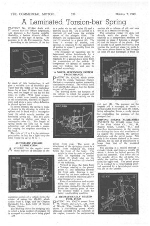
In actual practice, the spring is made as shown in the Idjiwing, in which the splined end is fitted with a rectangular head (1) which exactly matches the laminated spring (2). .The two parts are united by sliding over them a rectangular tube. (3). The length of spring inside the tube can be 'made adjustable, and will provide a means for varying the response according to the load.
The ratio of 15 to 1 is the minimum practicable: in fact, for a light lorry the ratio would be up to 50 to I.
• AUTOMATIC CHASSIS LUBRICATION
A SCHEME for the regular automatic delivery of lubricant to the
namerous points of a vehicle forms the subject of patent No 626,093, which comes from S. Edge, and the Clayton Oewandre Co., Ltd., both of Titanic Works, Lincoln.
The drawing shows the pumping unit in which a large number of plungers (1) is arranged in a circle, each being piped .a34
to a point via an exit valve (2) and a delivery union (3). Oil is carried in a reservoir (4) and keeps the working spaces of the plungers filled. The plungers are reciprocated bY a central rod (5) attached to a piston (6). The latter is worked by suction, and operates at intervals by the application of suction to space 7, possibly from the braking system.
The frequency of .operation can be determined either fortuitously by a valve attached •to the brake pedal, or regularly by a geared-down drive from , the transmission of the vehicle. If compressed air instead of suction be used for braking the unit can be modified accordingly.
• A NOVEL SUSPENSION; SYSTEM FROM FRANCE
D ATE NT No. 626,298, which comes
from M. Julien, Toulouse France discloses a suspension system possessing considerable novelty. The vehicle itself is of unorthodox design, but this forms no part of the patent.
The drawing shows the forepart of the vehicle, in which the engine and transmission are carried entirely on the driven front axle. The point of attachment of the springing system is a vertical front bulkhead (1), which forms the front of the body. The weight is taken by pairs of parallel links (2) supported by helical springs (3) which abut on the underside of brackets (4) attached to the bulkhead.
Viewed in plan, the links form a V-shape, meeting at the pivotal points (5) and spreading towards the front axle. Steering is performed by the usual rodwork, but a rack-and-pinion reduction gear is ,a1Sed instead of a worm.
Ease of manufacture and accessibility for repair are two of the advantages claimed for the scheme. Froth the running point of view the inventor makes a claim for better road-holding qualities.
A HYDRAULICALLY SEALED FUEL PUMP
PATENT No. 626,574 comes from W. Nicolls and C.A.V., Ltd., both of Warple Way, 'London, W.3, and shows a fuel-raising pump which, although operated by the camshaft of the engine, transmits the reciprocating
motion via a column of oil, and uses the oil as a means for sealing.
The actuating rocker (1) dots not directly work The piston (2), but employs as a compression member oil trapped in space 3 between a plunger (4) and the interior of the piston. The oil is kept in an tipper reservoir (5) and reaches the working apace via ports 6. The main piston' draws in fuel through an inlet (7) and discharges it from an
exit port (8). The pressure on the trapped _oil is arranged to reach a spring-loaded blow-off valve (9) which, being adjustable, forms a ready means for controlling the pressurn of the pumped fuel.
DRIVING ENGINE AUXILIARIES
PT EN T No. 625400,' comes r from .1 the Ford Motor Co.,. Ltd„ 88, Regent' 'Street, London, —W.I.; and describes improvements in themeans for driving the three vital auxiliaries of an engine—the oil-pump, the ignition distributor and the petrol pump. Not only is the scheme claimed to be more efficient, but its cost of manufacture is lower than 'that of the standard methods.
The drawing is. a section through a cylinder block, and shows a spindle (1) which is driven by helical gearing (2) fromthe camshaft. The lower end of the spindle drives the oil-pump (3), whilst -the ignition unit (4) is driven from the upper end. The petrol pump
(5) is worked by a reciprocating pushrod operated by a bevel-shaped eccentric (6) on the spindle.