


- IE END
Page 51
Page 50
Page 53
If you've noticed an error in this article please click here to report it so we can fix it.
OF THE
LOW-ROOF
DOUBLE-DECKER?
New Design of Bristol Chassis for Special SS-Seater Body with Central Gangway on Both Decks, But with an Overall Height of Only 13 ft. 2 ins. High Degree of Passenger Comfort
AMAJOR advance in the design of double-decker chassis, which may mean the extinction of the much-abhorred side-gangway body, is made in the prototype Lodekka model produced by the Bristol Tramways and Carriage Co., Ltd., Bristol. The unconventional chassis frame has been built for a special 58-seater body having central gangways, with full headroom on both decks and remaining within an overall laden height of 13 ft. 2 ins.
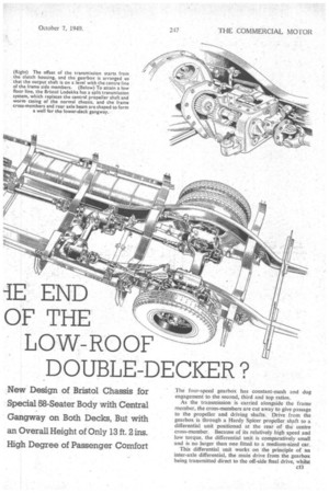
To fit a full-height double-deck body on a chassis and reduce the normal overall height by 12 ins, requires a radical change in approach to chassis design. The Bristol engineers have tackled the problem of covering the chassis line by 'using a downswept frame, offset gearbox, split transmission and twin drive to a rear axle with a downswept 1-section solid beam.
In the specially designed body, made by Eastern Coachworks, Ltd., Lowestoft, the chassis members form the floor frame for the lower deck, so that the laden height of the lower-deck gangway is only 1 ft. zli ins. above ground level.
Cantilever Body Mounting
The Lodekka frame side members are downswept from the engine rear cross-member and arched over the. final-drive units of the tear axle. There are four crossmembers, which are fabricated in the form of a hollowweb I-section, between the gearbox and tail of the chassis. The unusual feature of these members is that the top flanges are extended over the frame side members and cOmbined with outrigger brackets to form a cantilever mounting for the ,body. The top flange of each cross-member is arranged with a drop section at the centre to provide a well for the lower-deck gangway.
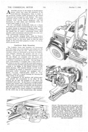
Apart from thesab floor and controls, there is nothing unusual in the design of the Chassis forward of , the clutch housing. The. standard Bristol A.V.W. 81-litre six-cylindered oil engine is supported in position by a three-point rubber mounting and equipped with a Bristol V.N.-type single-dry-plate clutch of 17-in. diameter, which has a special housing for securing the offset casing of the gearbox.
The arrangement of the gearbox and' primary-gear train permits the transmission to be offset 91 ins. towards the off side and dropped 6/ ins, below the crankshaft centre line. In this layout a straight-toothed primary gear meshes with a splined gear on the layshaft. The layshaft and mainshaft are parallel with the primary shaft and crankshaft, but the whole unit is inclined so that the height of the output coupling is approximately on the centre line of the chassis-frame side member. The four-speed gearbox has constant-mesh and dog engagement to the second, third and top ratios.
As the transmission is carried alongside the frame member, the cross-members are cut away to give passage to the propeller and driving shafts. Drive from the gearbox is through a Hardy Spicer propeller shaft to a differential unit positioned at the rear of the centre cross-member. Because of its relatively high speed and low torque, the differential unit is comparatively small and is no larger than one fitted to a medium-sized car.
This differential unit works on the principle of an inter-axle differential, the main drive from the gearbox being transmitted direct to the off-side final drive, whilst the opposing drive from the differential gearing .is. returned through a hollow shaft towards the gearbox. The hollow shaft conveys the drive, through a crossshaft and spiral-bevel gears, to the near-side wheel. Thus the conventional central propeller shaft is displaced by a split transmission line which employs twin
shafts alongside the frame members. A patent is pending for this form of transmission.
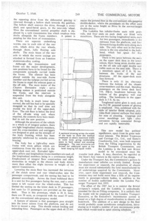
There are separate underslung worms, one to each side of the rear axle, which drive the rear wheels,, through short, . fully floating axle ,shafts The main beam of the rear axle to which the worm casings are attached is formed from an I-section 'aluminium-alloy casting.
Although the transmission and frame are the major developments, new.positions have to be found for the components normally carried inside the frame. The silencer has been placed outside the near-side frame member and the tailpipe carried across the frame to expel the exhaust gases at the off side. The main motor of the Clayton Dewandre triple servo braking system is positioned outside the frame, and the reservoir is suspended from the body alongside this unit.
As the body, is much lower than normal, the cab has had to be specially designed so that its roof does not exceed the level of the upper-deck floor. The cab floor is below the level of the off-side wing and, where required, the controls have been tnodified to suit the new position.
Although the structure of the vehicle as a whole is of integral pattern, there are light longitudinal chassis members, and the cross-members and outriggers are designed to pick up the strength of the body framing, -which has been specially reinforced by suitable crossbracing.
• The body has a light-alloy main frame with main pillars which are continuous from the skirt rail to the upper-deck cant rail. Extruded lightalloy pillars and longitudinal frame members are used, all the longitudinal members being in a continuous length. Employment of integral floor construction and other economies in Weight in the chassis and body details more than offset the slight increase in weight of the special transmission..
Lowering the Main floor has -increased the intrusion of the clutch cover and rear -wheel-arches into the passenger compartment, and the seating has had to be planned accordingly. Across the front bulkhead there is a seat for five passengers facing the rear, and a small space is left vacant over the wheel-arches. This has limited the seating on the lower deck to 25 passengers, but seats for 33 passengers are provided on the upper
deck. Thus in this prototype, which is 26 ft. long; there are 58 seats, as compared with the usual 55 seats on the conventional side-gangway model.
A feature of interest is that passengers pass straight into the lower saloon from the platform, and do not have to mount a step. This should reduce loading and unloading time. Passengers-on the upper deck sit 12 MC, nearer the ground than in the conventional side gangway double-decker, where the passengers on the offset seats are at the same height as those in the normal-height double-decker..
The Lodekka has tubular-frame seats with grab'rails, and four' seats on each deck are fitted with stanchions. There are two facing longitudinal seats, each for two passengers, immediately at the entrance from the platform; and four forward-facing double seats along each side. The only other seat in the lower saloon is the one attached to the bulkhead, which has space for fi..e passengers.
There is less space between the seats on the upper deck than in the lower saloon, there being seven double seats on the off side and eight double and treble seats on the near side. There is a minimum space of 2 ft. 3i between the backs of the seat structures. All the upper-deck seats face forward.
There is only 11 ins, clearance between the bottom of the chassis cross-members and the road. Standing passengers on the lower deck have 5-ft. 101-in. headroom between the bottom of the gangway well and ceiling. The headroom to the upper deck is 5 ft. Skins.
Toughened safety glass is used, and the E.C.W. patented system of glazing is employed. This, combined with the style of interior finish adopted, provides flush internal surfaces that inakfor ease of 'cleaning. Cappings and cover mouldings are light alloy extrusions having concealed fixings and are rapidly removable.
This new model has political significance, apart from its great tech nical interest. The Bristol Tramways and Carriage Co., Ltd., and Eastern Coachworks, Ltd., were both acquired from the Tilling organization by the British Transport Commission, and the Lodekka is the first new Bristol model to be announced since the transfer took place. It may, .therefore, be regarded as the State's first venture in the realms of bus design.
Under the Transport Act, the Commission's powers to manufacture road vehicles are strictly limited. Except for experiment or research, the production of chassis must not exceed substantially the total manufactured by all undertakings acquired by the Commission. Moreover, apart from experiment and research, the Corn'mission ,may not build more than a fifth of its requirements in passenger-vehicle bodies, in addition to the number of bodies authorized under the London Passenger Transport Act, 1933.
The effect of the 1947 Act is to restrict the Bristol company's output, and the Lodekka is undoubtedly intended for the ex-Tilling companies. It is unlikely that the model will be employed by the London Transport Executive, as the Executive's maintenance system is based on a high degree of standardization in chassis and . bodywork. The addition of a new design to the fleet would probably cause unwelcome complications, intro