 1
1 2
2 3
3 4
4 5
5 6
6 7
7 8
8 9
9 10
10 11
11 12
12 13
13 14
14 15
15 16
16 17
17 18
18 19
19 20
20 21
21 22
22 23
23 24
24 25
25 26
26 27
27 28
28 29
29 30
30 31
31 32
32 33
33 34
34 35
35 36
36 37
37 38
38 39
39 40
40 41
41 42
42 43
43 44
44 45
45 46
46 47
47 48
48 49
49 50
50 51
51 52
52 53
53 54
54 55
55 56
56 57
57 58
58 59
59 60
60 61
61 62
62 63
63 64
64 65
65 66
66 67
67 68
68 69
69 70
70 71
71 72
72 73
73 74
74 75
75 76
76 77
77 78
78 79
79 80
80 81
81 82
82 83
83 84
84 85
85 86
86 87
87 88
88 89
89 90
90 91
91 92
92 93
93 94
94 95
95 96
96 97
97 98
98 99
99 100
100 101
101 102
102 103
103 104
104 105
105 106
106 107
107 108
108 109
109 110
110 111
111 112
112 113
113 114
114 115
115 116
116 117
117 118
118 119
119 120
120 121
121 122
122 123
123 124
124 125
125 126
126 127
127 128
128 129
129 130
130 131
131 132
132 133
133 134
134 135
135 136
136 137
137 138
138 139
139 140
140 141
141 142
142 143
143 144
144 145
145 146
146 147
147 148
148 149
149 150
150 151
151 152
152 153
153 154
154 155
155 156
156 157
157 158
158 159
159 160
160 161
161 162
162 163
163 164
164 THE MARVELS OF MA GNETO MANUFACTURE I T is possible that
Page 82
Page 83
Page 84
If you've noticed an error in this article please click here to report it so we can fix it.
no machine ever made has called for more care in its design, in the selection of materials, and in manufacture than does the magneto, and that no magneto has received more care than that designed to withstand the arduous conditions of work of a commercial vehicle. The users of such machines cannot fail to be interested in learning a few facts about the methods employed in the production of this intricate instrument.
For this purpose we have selected the latest type of BJR magneto manufactured by C.A.V.-Bosch, Ltd. (a British company) at its works at Acton, London, W.3, where every particle of the various materials used, and all the labour employed, is British.
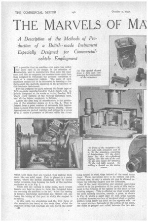
Almost the first step in manufacture is the production of the armature shown at B in Fig. 1. This is formed from a great number of extremely thin laminations stamped from sheet iron of special quality. These laminations are packed together and gripped in a press (Fig. 2) under a pressure of 30 tons, while the rivets which bold them fast are headed, thus making them seem like one solid mass. This is placed in a metal mould, where the molten aluminium alloy is forced Under pressure, thus forming the body of the machine as shown at A in Fig. 1.
" While this die casting is being made, flare bronze inserts are held in place to form the threaded holes for securing the machine to its bed. After the casting is formed, machining operations are carried out, one being the boring of the part in which the magnet is to rotate.
In this part, the aluminium and the iron faces of the armature are bored at the same time, whilst the registers of the ball bearings are also bored, the latter c32 being housed in steel rings instead of the usual brass rings. These operations have to be carried out with extreme care, as only a minute air gap is allowed between the rotating magnet and the armature.
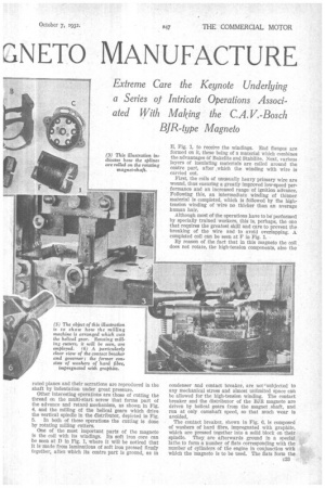
One of the most interesting and unusual operations carried on in the production of the parts of this instrument is the forming of the splines on the shaft of the rotating magnet. This is effected on what would seem the most unlikely machine, namely, a press, as shown in Fig. 3, whore a shaft may be seen lying against a vertical serrated surface of hardened steel, a similar surface being below the shaft on the opposite side. As the upper surface descends by the action of the press, the shaft is gripped and rolled between the two ser rated planes and their serrations are reproduced in the shaft by indentation under great pressure.
Other interesting operations are those of cutting the thread on the multi-start screw that forms part of the advance and retard mechanism, as shown in Fig. 4, and the milling of the helical gears which drive the vertical spindle in the distributor, depicted in Fig. 5. In both of these operations the cutting is done by rotating milling cutters.
One of the most important parts of the magneto Is the coil with its windings. Its soft iron core can be seen at D in Fig. 1, where it will be noticed that it is made from laminations of soft iron pressed firmly together, after Which its centre part is ground, as in E, Fig. 1, to receive the windings. End flanges are formed on it, these being of a material which combines the advantages of Bakelite and Stabilite. Next, various layers of insulating materials are coiled around the centre part, after „which the winding with wire is carried out.
First, the coils of unusually heavy primary wire are wound, thus ensuring a greatly improved low-speed performance and an increased range of ignition advance.
• Following this, an intermediate winding of thinner material is completed, which is followed by the hightension winding of wire no thicker than an average human hair.
Although most of the operations have to be performed by specially trained workers, this is, perhaps, the one that requires the greatest skin and care to prevent the breaking of the wire and to avoid overlapping. A completed coil can be seen at F in Fig. 1.
By reason of the fact that in this magneto the coil does not rotate, the high-tension components, also the condenser and contact breaker, are not ''subjected to any mechanical stress and almost unlimited space can be allowed for the high-tension winding. The contact breaker and the distributor of the BJ11 magneto arc driven by helical gears from the magnet shaft, and run at only camshaft speed, so that much wear is avoided,.
The contact breaker, shown in Fig. 6, is coMposed of washers of hard fibre, impregnated with graphite, which are pressed together into a solid block on their spindle. They are afterwards ground in a special lathe to form a number of flats corresponding with the number of cylinders of the engine in conjunction with Which the Magneto is to be used. The flats form the cam against which the contact breaker bears by spring pressure. This part is of the lightest possible construction to avoid inertia and to prevent flinging.
The bush on which the contact breaker pivots is made of a kind of fibre, which is not liable to contraction and, consequently, to become stiff on its pivot, as was so often the case with older patterns of magneto.
An interesting feature is the automatic advance and retard by means of the governor depicted in Fig. 6, in which the part carrying the hexagon cam shown is in the form of a sleeve, rotatable on the spindle but Controlled in relation to its spindle by the governor weights.
Normally, the hexagon cam lies in the position to retard, but as the speed increases and the weights fly outwards, it advances in relation to its spindle, thus automatically adjusting the timing by means of a spindle which does only the slight duty of carrying the contact breaker and distributor, instead of affecting the much heavier drive of the magnet. The pump-spark distributor for a six-cyindered engine is shown at C in Fig. 1.
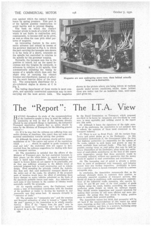
The testing department of these works is most complete, and specially constructed apparatus may be seen carrying out the most severe tests. The magnetos shown in the picture above are being driven at various speeds under severe conditions, whilst those behind them are under test for an indefinite time, until some part gives out.