


WET LINER ONCE OVER
Page 117
Page 118
If you've noticed an error in this article please click here to report it so we can fix it.
You might not think it but rebuilding a wet-linered engine is within the scope of most workshops — Colin Sowman gets to grips with a Scania 14-litre rebuild.
After almost 1.5 million kilometres the big vee-eight in Prince Transport's A-reg Scania needed some intensive care. -There was almost as much blow-by coming out of the breather as exhaust out of the pipe," says fitter Mike Holloway, The Scania spends most of its Lime on the Continent so it makes sense to put problems right at home rather than waiting for a costly foreign breakdown.
One Tuesday in October it rolled into Prince's Avonmouth workshop for an inframe overhaul. New pistons, liners, big ends and mains were to be fitted; the cylinder heads going for reconditioning.
On Wednesday morning Holloway started work, after disconnecting the inlet and exhaust manifolds and the water rail, the eight individual heads were removed. When drawing the pushrods out he gives them a shake to make sure the cam followers stay in place. The heads were taken to Price Brothers Engineering for reconditioning. Price Bros is also supplying Lhe engine components and some of the labour to remove and refit the wet liners.
Moving down the pit the sump is removed, all the big ends disconnected and the piston/con rod assemblies drawn out through the top. The main hearings remain in place for the moment.
When we arrived on the Thursday morning it was time to draw out the old liners. Given that the correct level of inhibitor has been maintained in the coolant a simple puller can be used, but if heavy corrosion has taken place a hydraulic unit may be needed to dislodge the liners. Once the seals are broken the liners can be pulled clear by hand. Inspect the liner seating recess in the top of the block. If this is pilled it will need recutting which requires specialised equipment.
AL the bottom of the water jacket are two large rubber 0-rings set into grooves in the block. These must be removed, after which the block can be cleaned. Holloway reckons it takes two hours per side to clean the block properly — the liner seating and 0ring recesses must be absolutely clean if the liners are to seal satisfactorily. Make sure the drain hole between the 0-rings is clear.
At this point Holloway was joined by Smith Bros engineer Alan Parsons who handles most of his employer's on-site work on both wet and dry linered engines.
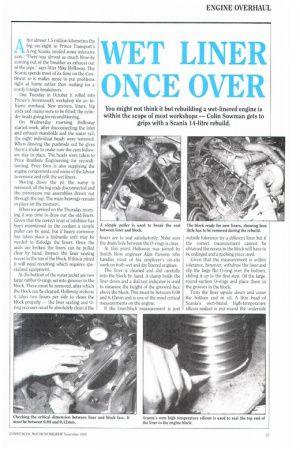
The liner is cleaned and slid carefully into the block by hand. A clamp holds the liner down and a dial test indicator is used to measure the height of the grooved face above the block. This must be between 0.08 and 0.12mm and is one of the most critical measurements on the engine.
If the liner/block measurement is just outside tolerance try a different liner but if the correct measurement cannot be obtained the recess in the block will have to be enlarged and a packing piece used Given that the measurement is within tolerance, however, withdraw the liner and slip the large flat 0-ring over the bottom, sliding it up to the first step. Oil the large, round-section 0-rings and place them in the grooves in the block.
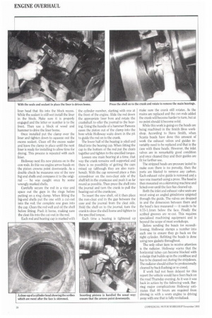
Turn the liner upside down and cover the bottom end in oil. A thin bead of Scania's own-brand high-temperature silicon sealant is put round the underside liner head that fits into the block recess. While the sealant is still wet install the liner in the block. Make sure it is properly engaged and the letter or number is to the front. Then use a block of wood and hammer to drive the liner home.
Once installed put the clamp over the liner and tighten down to squeeze out the excess sealant. Clean off the excess sealer and leave the clamp in place until the next liner is ready for installing to allow time for drying. This process is repeated with each liner.
Holloway next fits new pistons on to the con-rods. In this vee engine arrow heads on the piston crowns point downwards. As a double check he measures one of the new big end shells end compares it to the original — he was caught once by some wrongly marked shells.
Carefully secure the rod in a vice and space out the gaps in the rings before putting on a ring clamp. When fitting the big-end shells put the one with a cut-out into the rod: the complete one goes into the cap. Clean the rod well and oil the shell before fitting. Push it home, making sure the cleat fits into the cut-out in the rod.
Each rod and bearing cap is marked with the cylinder number, starting with one at the front of the engine. Slide the rod down the appropriate liner bore and rotate the crankshaft to offer the journal to the bearing. Using the handle of a hammer Parsons eases the piston out of the clamp into the bore while Holloway waits down in the pit to guide the rod on to the crank.
The lower half of the bearing is oiled and fitted into the bearing cap. When fitting the cap to the bottom of the rod put the cleats together and tighten to the specified torque.
Loosen one main bearing at a time, that way the crank remains well supported and there is no possibility of getting the caps mixed up (although they are also numbered). With the cap removed place a thin screwdriver on the non-cleat side of the shell left in the crankcase and push it as far round as possible. Then press the shell into the journal and turn the crank to pull the bearing out of the crankcase.
To insert the new shell, oil it then place the non-cleat end in the gap between the case and the journal from the cleat side. Hold the shell on to the journal, turn the crank to draw the shell home and tighten to the specified torque.
Each time a bearing is tightened up make sure the crank still rotates. As the mains are replaced and the con rods added the crank will become harder to turn, but at no point should it become solid.
While this work is going on the heads are being machined in the Smith Bros workshop, According to Steve Smith, when Scania heads have done this amount of work the exhaust valves and guides invariably need to be replaced and that is the case with these heads. However, the inlet valves are in remarkably good condition and once cleaned they and their guides are fit for further use.
The stripped heads are pressure tested to make sure there is no porosity, then the ports are blasted to remove any carbon. Each exhaust valve guide is removed and a new one inserted using a press. The head is then mounted on a skimming machine and licked over until the face has cleaned up.
Both the inlet and exhaust valve seats are recut using an angled grindstone spigoted through the guide. The valves are dropped in and the dimension between them and the head's face measured — it needs to be 0.75-1.1mm below the face. Finally the scribed grooves are re-cut. This requires specialised machining equipment and is beyond the scope of most workshops.
Before sending the heads for reconditioning, Holloway stamps a number into each one to ensure they go back on the right cylinder. Refitting the heads is done using new gaskets throughout.
The only other item to receive attention is the radiator. Holloway warns that the horizontal tubes can become blocked with a sludge that builds up in the crankbase and has to be cleaned out during the stripdown. The radiator should either be professionally cleaned by back flushing or re-cored.
If work had not been delayed for this report the vehicle would have been back on the road Thursday evening. As it was it was back in action by the following week. Barring major complications Holloway estimates that 40 hours are required from driving in with a worn engine to driving away with one that is fully revitalised.