 1
1 2
2 3
3 4
4 5
5 6
6 7
7 8
8 9
9 10
10 11
11 12
12 13
13 14
14 15
15 16
16 17
17 18
18 19
19 20
20 21
21 22
22 23
23 24
24 25
25 26
26 27
27 28
28 29
29 30
30 31
31 32
32 33
33 34
34 35
35 36
36 37
37 38
38 39
39 40
40 41
41 42
42 43
43 44
44 45
45 46
46 47
47 48
48 49
49 50
50 51
51 52
52 53
53 54
54 55
55 56
56 57
57 58
58 59
59 60
60 61
61 62
62 63
63 64
64 65
65 66
66 67
67 68
68 69
69 70
70 71
71 72
72 73
73 74
74 75
75 76
76 77
77 78
78 79
79 80
80 81
81 82
82 83
83 84
84 85
85 86
86 87
87 88
88 89
89 90
90 91
91 92
92 93
93 94
94 95
95 96
96 97
97 98
98 99
99 100
100 101
101 102
102 103
103 104
104 105
105 106
106 107
107 108
108 109
109 110
110 111
111 112
112 113
113 114
114 115
115 116
116 117
117 118
118 119
119 120
120 121
121 122
122 123
123 124
124 125
125 126
126 127
127 128
128 129
129 130
130 131
131 132
132 133
133 134
134 135
135 136
136 137
137 138
138 139
139 140
140 Improved Centrifugal Clutch
Page 98
If you've noticed an error in this article please click here to report it so we can fix it.
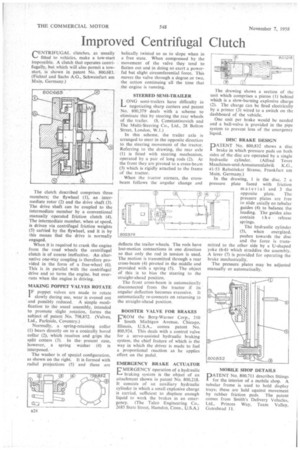
rENTR1FUGAL clutches, as usually
fitted to vehicles, make a tow-start impossible. A clutch that operates centrifugally, but which will also permit a towstart, is shown in patent No. 800,683. (Fichtel and Sachs A.G., Schweinfurt am Main, Germany.) The clutch described comprises three members; the flywheel (I), an intermediate rotor (2) and the drive shaft (3). The drive shaft can be coupled to the intermediate member by a conventional manually operated friction clutch (4). The intermediate member, when at speed, is driven via centrifugal friction weights (5) carried by the flywheel, and it is by this means that the drive is normally engaged.
When it is required to crank the engine from the road wheels the centrifugal clutch is of course ineffective. An alternative one-Way coupling is therefore provided in the form of a free-wheel (6). This is in parallel with the centrifugal drive and so turns the engine, but overruns when the engine is driving.
MAKING POPPET VALVES ROTATE
IF poppet valves are made to rotate slowly during use, wear is evened out ' and possibly reduced. A simple modification to the usual assembly, intended to promote slight rotation, forms the subject of patent No. 798,852. (Valves, Ltd., Parkside, Coventry.)
Normally, a spring-retaining collar (1) bears directly on to a conically bored collar (2), which receives and grips the split cotters (3). In the present case, however, a spring washer (4) is interposed.
The washer is of special configuration, as shown on the right. It is formed with radial projections (5) and these are helically twisted so as to slope when in a free state. When compressed by the movement of the valve they tend to flatten out and in doing so exert a powerful but slight circumferential force. This moves the valve through a degree or two, the action continuing all the time that the engine is running.
STEERED SEMI-TRAILER
LONG semi-trailers have difficulty in negotiating sharp corners and patent No. 800,379 deals with a scheme to eliminate this by steering the rear wheels of the trailer. (S. Constantinovich and The Multi-Steering Co., Ltd., 28 Bolton Street, London, W.1.)
In this scheme, the trailer axle is arranged to steer in the opposite direction to the steering movement of the tractor. Referring to the drawing, the rear axle (1) is fitted with steering mechanism, operated by a pair of long rods (2). At the front they are pivoted to a cross-beam (3) which is rigidly attached to the frame of the tractor.
When the tractor corners, the crossbeam follows the angular change and deflects the trailer wheels. The rods have lost-motion connections in one direction so that only the rod in tension is used. The motion is transmitted through a rear cross-beam (4) pivoted in the middle and provided with a spring (5). The object of this is to bias the steering to the straight-ahead position.
The front crosS-beam is automatically disconnected from the tractor if its angular deflection becomes excessive. It automatically re-connects on returning to the straight-ahead position.
BOOSTER VALVE FOR BRAKES L'ROM the Borg-Warner Corp., 310 South Michigan Avenue, Chicago, Illinois, U.S.A., comes patent No. 800,924. This deals with a control valve for a servo-assisted hydraulic braking system, the chief feature of which is the way in which the driver is made to feel a proportional reaction as he applies effort on the pedal.
EMERGENCY BRAKE ACTUATOR MERGENCY operation of a hydraulic braking system is the object of an attachment shown in patent No. 800,218. It consists of an auxiliary hydraulic cylinder in which a small explosive charge is carried, sufficient to displace enough liquid to work the brakes in an emergency. (The Talco Engineering Co., 2685 State Street, Hamden, Conn., U.S.A.) The drawing shows a section of the Unit which comprises a piston (1) behind which is a slow-burning explosive charge (2). The charge can be fired electrically by a primer (3) wired to a switch on the dashboard of the vehicle.
One unit per brake would be needed and a ball-valve is provided in the pipe system to prevent loss of the emergency liquid.
DISC BRAKE DESIGN
PATENT No. 800,832 shows a disc brake in which pressure pads on both sides of the disc are operated by a single hydraulic cylinder. (Alfred Teves Maschinen-und-Armaturenfabrik K.G., 41-53 Rebstificker Strasse, Frankfurt am Main, Germany.)
In the drawing, 1 is the disc, 2 a pressure plate faced with friction material and 3 the opposite plate. The pressure plates are free to slide axially on tubular guides (4) to balance the loading. The guides also contain t h e release springs.
The hydraulic cylinder (5), when energized, pushes towards the disc and the force is transmitted to the other side by a U-shaped yoke (6-6) which straddles the assembly. A lever (7) is provided for operating the brake mechanically.
The pressure plates may be adjusted manually or automatically.
MOBILE SHOP DETAILS
PATENT No. 800,711 describes fittings for the interior of a mobile shop. A tubular frame is used to hold display trays; these are held against movement by rubber friction pads. The patent comes from Smith's Delivery Vehicles, Ltd„ Princes Way, Team Valley, Gateshead 11.