


A Four-wheel-drive
Page 64
If you've noticed an error in this article please click here to report it so we can fix it.
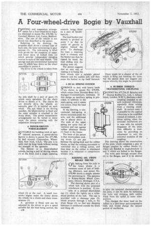
riRIVING and suspension arrange ments for a four-wheel-drive bogie are disclosed in patent No. 678,580, by Vauxhall Motors, Ltd., Luton, Bedfordshire. The rest of the vehicle is not shown nor described in the patent.
Referring to the drawing, the propeller shaft drives a normal type of back axle, the latter terminating in spur pinions (1). The axle-casing is fitted with pivots for the reception of upper and lower pairs of forked links (2) which provide independent swinging motion to each of the road Wheels. The springs used are conventional laminated ones (3) wIlith -bear down on the wheel
assemblies at points 4. • The drive to the wheels is taken from he axle shaft by a pair of gears (5) which carry sprockets for the chain drives as shown at 6. The chains do not directly drive the wheels; an epicyclic gear (7) is carried on each wheel. The sun wheel is the driving member, the planet-carrieris fixed and the outer annulus is attached to the brake drum. The power transmission arrangements can be varied in many ways, the patent covering only the suspension arrangements.
A POWER-DRIVEN WHEELBARROW QUITABLE for building work or agricultural purposes, a power-driven barrow is shown in patent No. 677,988, by Bell Aircraft Corporation, Wheatfield, New York, U.S.A. The aim is to carry and tip large loads without taxing % the strength of the 'operator.
The barrow is a three-wheeled 'vehicle, having a pair of driving wheels (1) at the front and a single castering wheel (2) at the rear: A small twostroke engine under the frame drives the wheels via a clutch and chain transmission (3).
A governor is fitted, and can be adjusted by the driver to give a speed suitable for the load being carried, the • A38 controls being fitted on a pair of handlebars (4). , The load bucket (not shown) is pivoted at point 5 so that its centre of gravity is slightly behind • the pivot. To discharge the load, a retaining latch is released, and the 'bucket can then be tipped by hand, the load sliding over the sloping nose (6).
The patent suggests that an easy way of tipping is to bump the front wheels into a suitably placed obstacle and the sudden jerk will then cause the bucket to tip itself forward.
A DUAL SPRING SYSTEM
QPRINGS to deal with heavy loads 16-J are shown in patent No. 679,098, which comes from Daimler-Benz A.G., Stuttgart-Untertiirkheim, Germany. In this design an auxiliary .spring is proSt vided, in addition to the
,main spring, and it comes into action when the load increases.
In the drawing, a conventional leaf-spring is shown mounted under the axle, and the additional one is placed above it. The ends of the upper spring are quite free of restraint and rest against rubber abutment blocks (1) fixed to the frame.
The basis of the patent is that intermediate rocking levers (2) are put between the spring-ends and the rubber blocks, so that the rubbing movement is converted into a rolling action, and thus wear on the rubber is eliminated becanse it is subjected to compression stresses only.
KEEPING OIL FROM BRAKE DRUMS
Oa leaking from the axle to the brake drums is a common cause of loss of braking efficiency, and patent No. 678,908 shows.a simple, scheme for preventing it. The patentee is Kelsey-Hayes Wheel Company, Detroit, Michigan, U.S.A. '
The drawing shows part of a wheel hub with the proposed attachment in position. It consists of a pressed sheet-metal cap ( f), which fits tightly on a cylindrical portion of the hub. The cap is provided with, a drainage pipe (2); which projects through a hole in the drum flange (3), so that any escaping lubricant is conducted outside the drum and flung off. here might be a chance of the oil ich is flung out reaching the tyres, t the patent does not suggest any ans whereby this might be prevented.
A RUBBER TORQUETRANSMITTING COUPLING ATENT No. 677,736 (P. Brierley and Dunlop Rubber Co.' Ltd., 1, Albany eet, London, N.W.1), discloses a shaft coupling intended to absorb torsional vibrations, especially those arising from a running crankshaft. In certain cases it is possible for the applied vibrations to be amplified instead of reduced, a condition arising when the torsional oscillations are in tune with the natural frequency of the joint. This difficulty is overcome by providing an adjustment to vary the torsional modulus of the coupling.
he drawing shows the construction of the joint, which comprises a pair of fla ges coupled by rubber blocks (I). T se are bonded to anglezbrackets (2 an 3) which are bolted to the flanges.
he bolts path through arcuate slots (4) in the flanges, and if it be desired to alter the torsional characteristics of th joint, it can be done by loOsening -th bolts and swinging each rubber ht ck from the radial to some other po iLion.
his changes the shear load on the rut her to a part-shear part-compressive load, and would change the natural period of oscillation.