


HINTS ON MAINTENANCE.
Page 30
Page 31
If you've noticed an error in this article please click here to report it so we can fix it.
How to Get the Best Out of a Vehicle, to Secure Reliability and to Avoid Trouble.
CONTRIBUTIONS are invited for this page from fleet managers, drives, garage foremen, and mechanics, works staff and draughtsmen, and will be paid for on a generous scale. Every system, make, and type of commercial Motor vehicle will be dealt, with, and the matter should be written with a view to the disclosure of workshop and garage practice in the maintenance of a vehicle—practices
which., whilst they may be quite normal, are peculiar to the particular vehicle and may not be: generallyknown to those responsible for its running. Expe
dients and suggestions for overcoming roadside and other troubles are covered in the following page, dealing with letters from our driver and mechanic readers. Communications should be addressed to " The Editor, The Commercial Motor, 7-15, Rosebery Avenue, London, E.O.l."
287.--Repositioning. the Oil Relief Valve on • Tylor Engine of A.E.C.
We have received an interesting and instructive letter from the Service Section of the Associated Equipment Co., Ltd., in connection with Hint on Maintenance, No 254, entitled " Big-end Trouble on Tyler Engines." It was suggested in this Hint that the removal of the internal release valve on the Tyler engine, and the plugging up of the hole, allow too great an oil pressure, and in this opinion the makers. concur.
As was then stated, the relief valve is constantly operating except when the oil is hot and the engine running very slowly, and the excessive pressure causes heavy oil consumption, as, naturally, it escapes in large quantities from the hearings, especially when the latter are in anything but excellent condition, and also quantities of it get above, the pistons.
The suggested alteration of the position of the relief valve makes this much more accessible and, as a matter of fact, it was realized by the builders of the A.E.C. lorry some considerable time ago, how difficult it is to remove the valve from inside the engine, and special parts -were therefore made to enable it to be brought to an outside position.
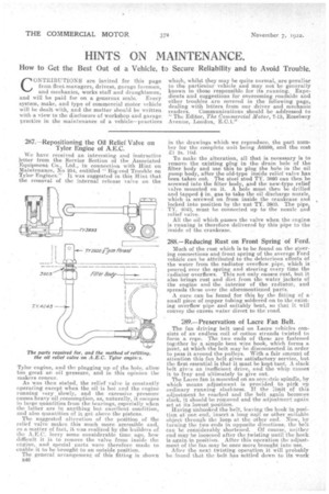
The general arrangement of this fitting is shown B46 in the drawings which we reproduce, the part number for the complete Unit being A6599, and the cost £1 2s. 10d.
To make the alteration, all that is necessary is to remove the existing plug in the drain hole of the filter body and use this to plug the hole in the oil pump body, after the old-type inside relief valve has been taken out. The steel stud TY. 3B93 can then be screwed into the fitter body, and the new-type relief valve mounted on it. A hole must then be drilled and tapped in. gas to take the oil discharge nozzle, which is screwed on from inside the crankcase and locked into position by the nut T.Y. 3903. The pipe, TY. 4043, must be connected up to the nuzzle and relief valve.
All the oil which passes the valve when the engine is running is therefore delivered by this pipe to the inside of the crankcase.
288.—Reducing Rust on Front Spring of Ford.
Much of the rust which is to be found on the steering connections and front spring of the average Ford -vehicle can be attributed to the deleterious effects of the water from the radiator overflow pipe, which is poure4 over the spring and steering every time the radiator overflows. This not only causes rust, but it also brings rust and dirt from the, water jackets of the engine and the interior of the radiater, and spreads these over the aforementioned parts.
A cure can be found for this by the, fitting of a small piece of copper tubing soldered on to the existing overflow pipe and suitably bent, so that it will convey the excess water direct to the road.
289.—Preservation of Lacre Fan Belt.
The fan driving belt used on acre vehicles con si ', sts of an endless coil of cotton strands twisted to form a rope. The two ends of these are fastened together by a simple bent wire book, which forms a joint, at which the belt may be disconnected in order to pass it around the pulleys. With a fair amount of attention this fan belt gives satisfactory service, but the first essential is that it must be kept taut. A slack belt gives an inefficient drive, and the whip causes it to fray and ultimately to give out. The La,cre fan is mounted on an ecneetric spindle, by which means adjustment is provided to pick up ordinary running slackness. If the limit of this adjustitent be reached and the belt again becomes 8lack, it should be removed and the adjustment again set at its lowest position. Having unhooked the belt, leaving the hook in posi, lion at one end, insert a long ne.il or other suitable object through the loop at the other end. Now, by turning the two ends in opposite directions, the belt can be considerably shortened. Of course, neither end may be loosened after the twisting until the hook is again in position. After this operation the adjustment of the fan may be once more brought into use.
After the next twisting operation it will probably be found that the belt has settled down to its work and lost its stretch, so that adjustment is less frequently required and much time saved.
A point to watch is the fastening of the wire hook to see that it is passed through the centre of the beltend loop so that it is encircled by all the cotton strands.
290.—An Adjustable .Magneto Coupling for the JB4-type Tytor Engine.
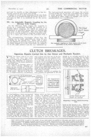
On. the JB4-type Tylor engine the magneto is driven by a cross-shaft through the medium "of a flexible fabric coupling, for which no means of adjustment is provided except that of altering the skew gear on the cross-shaft. The latter has a flat filed on it and the 'spider or coupling is held in position by a taper pin which is also provided with a fiat.
The accompanying illustration shows how the. coupling can be made adjustable by filing the pin as shown by the dotted line. When this is done the pin should be placed in position in the coupling, the latter slipped on to the er'oss-shaft, the magneto set to the right position and the nut tightened up. The last-mentioned operation will cause the curved portion of the pin to nip the cross-shaft and to hold it quite securely. The alteration can, of course, be applied to other makes of engines, and can. be accomplished very expeditiously.