


A Manual cum Power Steering System
Page 48
If you've noticed an error in this article please click here to report it so we can fix it.
cROM Bendix Aviation Corporation,
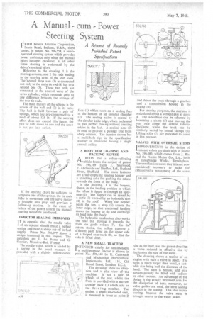
South Bend, Indiana, U.S.A., there comes, in patent No. 596,558, a servooperated steering system which provides power assistance only when the manual effort becomes excessive; at all other times steering is performed by the driver's unaided effort.
Referring to the drawing, 1 is the steering column, and 2 the rods leading to the steering arms of the stub axles. The 'normal drop arm (3) is connected not only to the main tie rod (4) but to a second one (5). These two rods are connected to the control valve of the servo cylinder, which responds only to any difference between the settings of the two tie rods.
The main feature of the scheme is the action of the ball end (7) in its tube. The ball is held between a pair of springs, which are pre-compressed to a load of about 125 lb. If the steering effort does not exceed this figure, the two tie rods move as one and the servo is not put into action.
If the steering effort be sufficient to compress one of the springs, the tie rods differ in movement and the servo motor is brought into play and provides a follow-up motion. In the event of failure of the power system the manual steering would be unaffected.
INJECTOR SEALING IMPROVED IT is essential that the needle valve .1 of an injector should make a perfect seating and have a sharp cut-off in fuel supply. Patent No. 596,077 shows a design improved in this respect. The patentees are L. Le Bozec and G. Gautier, Mesnil-le-Roi, France.
The needle valve, which is loaded by a spring in the usual manner, is provided with a slightly hollow-coned
face (1) which seats on a scaling face at the bottom of an annular chamber (2). The sealing action is caused by the circular knife-edge, which is claimed to give perfect closing without Creating eddies in the fuel. A conical nose (3) is used to provide a passage free from sharp' corners. The injector shown has a multi-hole tip; in the specification another is illustrated having a single central orifice.
A BODY FOR LOADING AND PACKING REFUSE
A BODY for a refuse-collecting Pi, vehicle forms the subject of patent No. 596,169 from J. Sherwood, F. Alkhurch and Shefflex, Ltd., Rutland Street, Sheffield. The main features are a self-emptying loading hopper and a travelling rake for packing the refuse towards the front of the body.'
In the drawing; 1 is the hopper, shown in the loading position in which the refuse is tipped in through an aperture (2). The hopper can be raised ,by a cable (3) worked by an hydraulic ram (4) in the roof. When the hopper nears the top, a stop (5) arrests the inner edge, so that continued hauling causes the hopper to tip and discharge its load into the body.
The hydraulic mechanism also works the rake (6), moving it towards the front on guide rollers (7). On the* return stroke, the rollers traverse a diferent path lying on the upper side of a looped cam-track. (8), so that the rake is lifted clear.
A NEW SMALL TRACTOR INTENDED chiefly for smallholders, a multi-purpose tractor is shown in patent No. 596,148 by R. Cattanach — and Mechanised Horticultural Implements, Ltd., • 116, Old Broad Street, London, E.C.2. The drawings show an elevalion and a plan view of the machine. It has a pair of wheels at the rear, whilst the f I) front is provided with a narrow crawler track (I) which acts as the dr iv ing member. The engine, a small air-cooled unit, — is mounted in front at point 2 and drives the track through a gearbox and a transuaission housed in the casing • (3).
For steering purposes, the machine is articulated about a vertical axis at point 4, The wheelbase can be adjusted by loosening a clamp (5) and moving the rear axle along the central tubular backbone, whilst the track can be similarly varied by lateral clamps (6). Lifting stilts (7) are provided to assist in this purpose.
VALVES WITH OVERSIZE. STEMS IMPROVEMENTS in the design of 'exhaust valves are dealt with in patent No. 596,480, which comes from J. Rix and the Austin Motor Co., Ltd., both of Longbridge Works. Birmingham. The specification states that it is not now considered ' necessary to make the exhaust-valve passageway of the same size as the inlet, and the patent describes a valve reduced in effective size by incfeasing the size of the stem.
The drawing shows a section of an engine with such a valve in place. The stem is much larger than usual, a suitable size being half the diameter of the head. The stem is hollow, and may advantageously be filled with sodium or other coolant. An advantage of the design is the greatly increased area for the dissipation of heat; moreover, no valve guides are used, the stem sliding directly in the casting, This also assists cooling, because the valve stem is brought nearer to the water jacket.