


A New Trolleybus
Page 36
Page 37
If you've noticed an error in this article please click here to report it so we can fix it.
for Exceptional Conditions
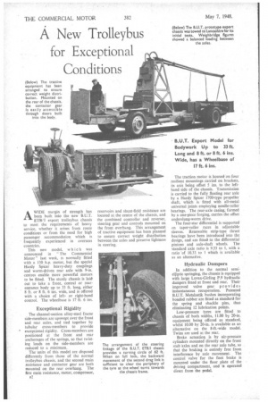
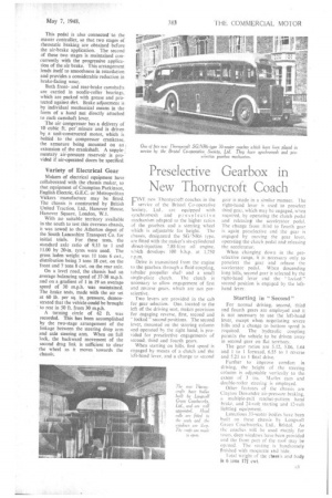
AWIDE margin of strength has been built into the new B.U.T. ETB/I export trolleybus chassis to meet the requirements of heavy service, whether it arises from route conditions or from the need for high passenger accommodation which is frequently experienced in overseas countries.
This new model, wh lc h was announced in The Commercial Motor" last week, is normally fitted with a 130 h.p. motor, but the special Hardy Spicer heavy-duty couplings and worm-driven rear axle with 9-in. centres enable more powerful motors to be fitted. The sturdy chassis is laid out to take a front, central or rearentrance body up to 33 ft. long, either 8 ft. or 8 ft. 6 ins, wide, arid is offered with a choice of leftor right-hand control. The wheelbase is 17 ft. 6 ins.
Exceptional Rigidity
The channel-section alloy-steel frame side-members are upswept over the front and rear axles, and tied together by tubular cross-members to provide • exceptional rigidity. Cross-members are positioned at the front and rear anchorages of the springs, so that twisting loads on the side-members are reduced to a minimum.
The units of this model are disposed differently from those of the normal trolleybus chassis, and the second main resistance and contactor gear are both mounted on the rear overhang. The first main resistance, motor, compressor, 132. reservoirs and shunt-field resistance are located at the centre of the chassis, and the combined controller and reverser, steering gear and controls mounted on the front overhang. This arrangement of tractive equipment has been planned to ensure correct weight distribution between the axles and preserve lightness in steering.
The traction motor is housed on four resilient mountings carried on brackets, its axis being offset 5 ins, to the lefthand side of the chassis. Transmission is carried to the fully floating rear axle by a Hardy Spicer I700-type propeller shaft, which is fitted with all-metal universal joints employing needle-roller bearings. The rear-axle casing, formed by a one-piece forging, carries the offset underslung-worm drive.
The four-star differential is supported on taper-roller races in adjustable sleeves. Renewable strip-type thrust bearings have been introduced into the design, and are fitted to the differential pinions and axle-shaft wheels. The standard axle ratio is 9.33 to 1, with a ratio of 10.33 to 1 which is available as an alternative.
Hydraulic Dampers
In addition to the normal semielliptic springing, the chassis is equipped with large Luvax-Girling P.9 hydraulic dampers fitted at front and rear. Their improved valve gear provides instantaneous recuperation. Patented B.U.T. Metalastik bushes incorporating bonded rubber are fitted as standard for the spring and shackle pins, thus eliminating 12 lubrication points.
Low-pressure tyres are fitted to chassis of both widths, 11.00 by 20-in. equipment being offered as standard, whilst 10.00 by 20-in, is available as an alternative on the 8-ft.-wide model. Twins are used at the rear.
Brake actuation is by air-pressure cylinders mounted directly on the front stub axles and on the rear axle tube, so that the braking is entirely free from interference by axle movement. The control valve for the foot brake is mounted under the floor plate of the driving compartment, and is operated direct from the pedal.
This pedal is also connected to the master controller, so that two stages of rheostatic braking are obtained before the air-brake application. The second of these two stages is maintained concurrently with the progressive application of the air brake. This arrangement lends itself to smoothness in retardation and provides a considerable reduction in brake-facing wear.
Both frontand rear-brake camshafts are carried in needle-roller bearings, which are packed with grease and protected against dirt. Brake adjustment is by individual mechanical means in the form of a hand nut directly attached to each camshaft lever.
The air compressor has a delivery of 10 cubic ft. per' minute and is driven by a unit-constructed motor, which is bolted to the compressor crankcase, the armature being mounted on an extension of the crankshaft. A supplementary. air-pressure reservoir is provided if air-operated doors be specified.
Variety of Electrical Gear
Makers of electrical equipment have collaborated with the chassis maker, so that equipment of Crompton Parkinson, English Electric, G.E.C. or Metropolitan Vickers ' manufacture may be fitted. The chassis is constructed by British United Traction, Ltd., Hanover House, Hanover Square, London, W.I.
With no suitable territory available in• the South to test this overseas chassis, it was towed to the Atherton depot of the South Lancashire Transport Co. for initial trials. For these tests, the standard axle ratio of 9.33 to 1 and 11.00 by 20-in. tyres were used. The gross laden weight was 11 tons 6 cwt., distribution being 3 tons 18 cwt. on the front and 7 tons 8 cwt, on the rear axle.
On a level road, the chassis had an average balancing speed of 37-38 m.p.h. and on a gradient of I in 19 an average speed of 30 m.p.h. was maintained. The brake tests, made with the air set at 60 lb. per sq. in. pressure, demonstrated that the vehicle could be brought to rest in 50 ft. from 30 m.p.h.
A turning circle of 62 ft. was recorded. This has been accomplished by the two-stage arrangement of the linkage between the steering drop arm and axle steering arm. When on full lock, the backward movement of the second drag link is sufficient to clear the wheel as it moves 'towards the chassis.